FAQ
Over time I’ve answered quite a few questions in the Shaders (and URP) channels on the Official Unity Discord (as well as my own discord). But one problem with using discords over regular forums, is those answers are no longer searchable through Google - so I’ve made this page!
- (Also so I can link here when the questions get asked again, rather than having to repeat myself)
- Will update when I see other frequent (or just interesting) questions come along!
- Use the browser Find function (Ctrl+F) to search for keywords (in titles).
- If you want to search in answers too, Click Here to expand all foldouts first.
- Click buttons below to foldout answers! This also changes the URL so you can link to them! :)
Sections :
- General Unity
- Shader Graph (Issues / Workarounds)
- Shader Graph (Examples / Snippets)
- Shaders (HLSL/ShaderLab and info common to both code/graphs)
General Unity
You’ll commonly see your materials turn magenta if you’ve tried switching to a different render pipeline. This occurs because each pipeline uses different shaders.
You can automatically convert any materials using Unity’s shaders (e.g. Standard) :
- URP (2021.2+) : RP Converter Window
- URP (older versions) : Upgrading Materials
- HDRP : Render Pipeline Wizard
Any custom shaders (that you’ve written or from downloaded assets) cannot be converted automatically. You would need to rewrite them or a find a replacement asset.
If you aren’t upgrading, materials can also turn magenta when there is an error in the shader syntax (Should be able to see these in the Console, or in the Inspector when the shader asset is selected).
If a magenta material is using a Shader Graph, be sure the target is assigned correctly, and save the graph using the Save Asset button in the top left of the shader graph window.
In a build, magenta materials could also mean the shader uses a compile target which is higher than what is supported by the platform.
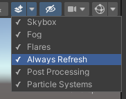
By default the Scene View does not constantly re-render it’s camera to help with editor performance.
If requried though, there’s a dropdown in the top right where you can enable “Always Refresh” (or “Animated Materials” in older versions)
Correctly sorting transparent geometry can be difficult. It’s basically an unsolved problem in realtime computer graphics. There usually isn’t a single answer that can solve every case.
Opaque objects don’t have this problem as they write to the Depth Buffer (ZWrite), which allows Depth Testing (ZTest) to occur to sort on a per-fragment/pixel basis. Unity also will render opaque objects closer to the camera first, so we don’t need to waste time rendering pixels behind others.
But with the Transparent queue, shaders typically don’t write to the depth buffer and we have to render objects further away first, in order to achieve the correct Alpha Blending. Even if depth write was enabled, it still wouldn’t sort correctly when blending is involved.
Quick tips :
- Always split Opaque and Transparent parts of a model into separate meshes (or at least separate sub-meshes) and apply separate materials.
- If your object doesn’t need partial transparency, consider using Opaque with Alpha Clipping instead.
- In HLSL, use
clip(alpha - threshold)orif (alpha < threshold) discard; - In Shader Graph, can find this in Graph Settings
- This could also be paired with Dithering to fake some transparency. For example, see this Shader Graph tutorial by Daniel Ilett
- In HLSL, use
- In some cases, can swap to a different blend mode. Additive (
Blend One One) and Multiplicative (i.e.Blend Zero SrcColor) blending modes in particular would produce the same results regardless of the order those objects are rendered in!
Solutions to fixing common transparent sorting issues are listed below.
Render Queue
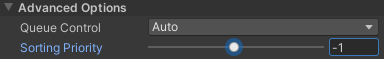
Transparent objects will sort based on their mesh origin. If you know that a particular transparent material should always appear behind / on top of others, you can use the Render Queue or Sorting Priority on the material to force the render order.
Pre-sorting Mesh Triangle Order
When rendering a mesh, the faces are rendered in order of their indices/triangles array. In cases where you don’t have intersecting geometry, it may be possible to pre-sort the triangles to force the draw order. This can be more performant than using the above method, but requires some setup in the modelling program.
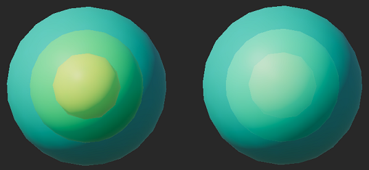
A mesh consisting of layered spheres.
Left : The inner spheres are incorrectly rendering on top.
Right : Sorting corrected by combining layers in specific order in Blender.
It may vary in each 3D modelling program, but as you combine multiple meshes, the assumption is that the triangles are appended.
Example in Blender :
- Separate each “layer” of triangles into separate objects.
- Select two layers - outer most layer first. I find it easiest to do this in the Outliner while holding Ctrl
- Combine/Join with Ctrl+J (while hovering over the 3D Viewport)
- Repeat steps 2 & 3 until each layer is collapsed down into a single mesh
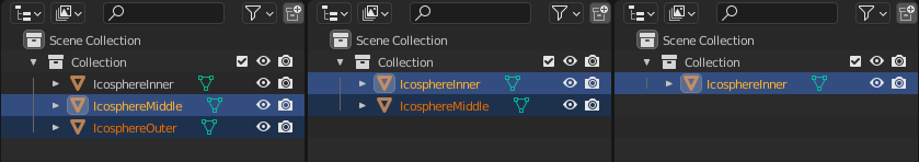
Blender Outliner, showing each layer being combined after repeating these steps.
- Note that using some Modifiers could change the triangle ordering.
- You would want to keep using
Cull Backwith this method. If you need back faces you’d need to duplicate the geometry will flipped faces/normals, and sort these triangles appropriately. - May also need to untick the “Optimise Mesh : Polygon Order” on the model import in Unity. As this may reorganise the triangle order.
Transparent Depth Prepass
When you don’t want to see overlapping faces of the model through itself, we can use a prepass to write to the depth buffer only. When we then render our object normally it can ZTest against this.
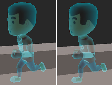
Left : Normal Render
Right : Render with Prepass
(Character from Kenney Animated Characters 2)
For Built-in RP, can add a pass before your main one :
|
|
(Can find another example here : https://forum.unity.com/threads/transparent-depth-shader-good-for-ghosts.149511/)
In other pipelines we can’t use multi-pass shaders, but you can instead use a separate shader/material with -1 on the Sorting Priority (or Render Queue). Can use the following code in a .shader file (Create → Unlit Shader)
|
|
- Can then attach it as a second material on the Mesh Renderer.
- If the mesh already has multiple sub-meshes / materials, may be better to separate that part of the mesh and use another GameObject & MeshRenderer too.
- For URP, if you have many objects that need this prepass, then rather than using multiple materials / GameObjects, you can use the Render Objects feature. This allows us to re-render a particular Layer with an Override Material (using our DepthPrepass shader)
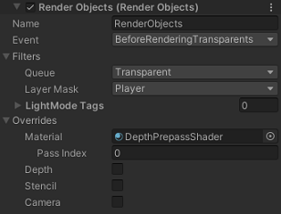
- But note that using this removes the ability to see any other transparent objects through the mesh. (Unless they are moved to the Before Rendering Transparents event too)
OIT
There are also methods to achieve Order Independent Transparency - But I’m not at all familiar with these. I think they’re quite expensive (either in terms of performance or memory), and Unity does not include any support for them so you’d need to implement this stuff yourself (or find an asset/package that handles it for you. This would require custom shaders too though, so not easy to implement)
2021.2+ versions of the URP have a Depth Priming option on the Universal Renderer Asset while using the Forward path. In the URP template this is set to Auto (enabled if URP is already doing a Depth Prepass rather than a CopyDepth pass. Can check Frame Debugger to see what is used)
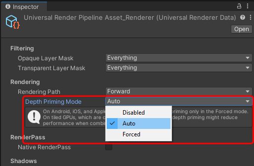
Depth Priming allows rendering opaque objects with a Depth Prepass, to populate the depth buffer without the fragment shading cost - potentially reducing the cost of overdraw in the opaque stage.
It requires shaders to have a pass with the DepthOnly LightMode tag in the shader (and DepthNormals if using a renderer feature that requires the Camera Normals Texture - such as SSAO or Decals). If a shader doesn’t have these passes, the forward pass is still rendered (but with ZWrite Off) and the skybox later draws over it, hence it appears invisible.
For example of how to set these passes up, see the templates here : https://github.com/Cyanilux/URP_ShaderCodeTemplates/
You could instead set Depth Priming to Disabled, which will make the object visible. However without the DepthOnly/DepthNormals passes, objects still may not appear in the Camera Depth Texture (Scene Depth node) or Camera Normals Texture.
An alternative is using Shader Graph, which will generate the passes required by URP.
OnRenderImage does not work in URP.
If you are using it to apply image effects with Graphics.Blit, In 2022.2+ should use the Fullscreen Pass Renderer Feature and Fullscreen Graph - or custom shader including Blit.hlsl. Use the Vert function as the vertex shader and call FragBlit in your fragment shader.
For prior versions, can use my Blit Renderer Feature.
For effects that require more than just a Blit, may need to write your own Custom Renderer Feature - my post on them may help (aimed at 2022+).
If you want to edit materials from imported models in Unity, you need to extract those materials before they can be edited. Click on the model file in the Project window under your assets, then the Materials tab in the Inspector. Should be a button to extract there.
Alternatively / For models with no materials / or for Unity default objects (Cube, Sphere, Capsule, etc) :
- Unity will automatically assign a default material which cannot be edited. You need to create your own material instead. In the Project window under your assets, right-click and select Create → Material. Choose an appropiate shader from the dropdown and adjust properties. Then drag the material onto the object, or assign it under the Renderer component (e.g. MeshRenderer, SpriteRenderer, UI Image, etc.)
As of Unity 2022, Shader Graph automatically generates a Material under each graph asset. These materials cannot be edited from Unity’s Inspector, but uses the default values assigned to properties within Shader Graph. To adjust them, select the property in the Blackboard and edit the Default field in the Graph Inspector window inside Shader Graph.
If you want a Material with values different than the defaults, you need to create a new Material asset using the shader. In the Project window under your assets, right-click the Shader Graph Asset then select Create → Material.
Shader Graph (Issues / Workarounds)
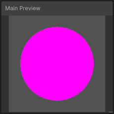
The Main Preview showing as Magenta/Pink usually means that the graph Target is not supported in the current Render Pipeline. This can be found under the Graph Settings tab of the Graph Inspector window - which you can toggle with a button in the top right of the graph.
If you have created a “Blank Shader Graph” you would also need to add a target to that list before you can use the graph on a material.
In 2021.2+ it is possible to add the Built-in RP as a target. Older verisons do not have support for Built-in and must use URP or HDRP. Once the URP or HDRP package is installed, there is more that is required to properly configure Unity to use those pipelines, such as assigning a pipeline asset under Project Settings.
See the documentation for steps (can select version in top left of these pages) :
- URP : Install URP into a Project
- HDRP : Upgrading to HDRP
If you have already done this, check the Target (under the Graph Settings tab of the Graph Inspector window). Make sure this matches the the pipeline you have installed & configured. Then save the graph using the Save Asset button in the top left.
May be able to find more information in my Intro to Shader Graph post.
Note that you may also see other previews showing as Magenta/Pink when obtaining undefined values (NAN), such as when dividing by zero, or using negative values in the Power node (as the hlsl pow function only supports positive ranges).
In v10+ (Unity 2020.2+), you can obtain a redirect node by double left-clicking a connection wire. Or right-click and select “Add Redirect”.
This is intentional. Previews inside nodes do not show alpha/transparency, only the RGB data. It’s common for colours to “stretch out” in fully transparent areas to avoid artifacts. If it was instead black in these areas, the colour might darken along the transparent edge. (That may look even worse when dealing with mipmaps, though you typically wouldn’t have those with sprites in particular)
Only the Main Preview will show transparency.
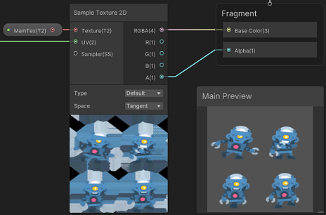
(Robot Character from Kenney Toon Characters 1)
Even with these stretched-out previews, the final result should look correct provided the alpha channel (A output from Sample Texture 2D) is connected to the Alpha port in the Master Stack.
- If you don’t see that port (or it is greyed out), your graph is currently set to be Opaque. Can change this to Transparent in the Graph Settings (tab of Graph Inspector window, toggled with button in top right of graph). Sprite graphs are always transparent by default.
- If you still don’t see the Alpha port, try adding the block manually (see Intro to Shader Graph post - Master Stack)
If for some reason you do need the texture masked correctly to the alpha, can Multiply the RGBA and A outputs. Or if you need to control the background color, put the A output into the T input on a Lerp with A as the background and B as the RGBA output.
Some nodes can only be connected to the Fragment stage.
- The Is Front Face node uses the
SV_IsFrontFacesemantic which is only available as an input to the fragment shader. This should make sense, as the vertex shader runs on vertices - which do not have any information about how they connect or the faces yet. - Partial screen space derivative functions (DDX, DDY, DDXY) are also only supported by the fragment shader, as they compare values for neighbouring fragments/pixels.
Shader Graph does not make this problem very clear, but it is most commonly encountered when dealing with the Sample Texture 2D node, which uses these derivatives behind the scenes to calculate the mipmap level when sampling. You would instead need to use the Sample Texture 2D LOD version.
There are other nodes that rely on the derivates, such as Normal From Height and the various procedural shapes (e.g. Ellipse, Rectangle, Polygon, Rounded Rectangle, Rounded Polygon).
There are also nodes that use SAMPLE_TEXTURE2D(tex, sampler, uv) in their code (e.g. Triplanar), but these could likely be rewritten manually via a Custom Function node to use the SAMPLE_TEXTURE2D_LOD(tex, sampler, uv, lod) macro instead, in order to support the vertex shader. (Can view generated code for a specific node by right-clicking it and selecting Show Generated Code or Open Documentation)
For more information / nodes affected, see Intro to Shader Graph post - Fragment-Only Nodes
Editing Vertex Positions does not automatically change the Normal Vectors, which are required to affect shading.
I have a few methods on how to calculate new normals listed here : Vertex Displacement post - Recalculating Normals
This occurs because the Normal vectors stored in the mesh are intended for the front faces only. We can flip them for back faces by making use of the Is Front Face and Branch nodes.
If using a Normal Map, we would use the result of our Sample Texture 2D in the True input, and Multiply it by (1, 1, -1) for the False input. This would then go into the Normal (Tangent Space) port on the Fragment stage of the Master Stack.
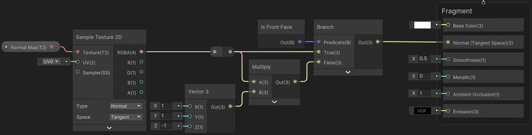
If not using a Normal Map, we could use the Normal Vector node in Tangent space - or just a Vector3 set to (0, 0, 1) as those will be equal…
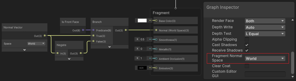
But it should actually be cheaper to change the Fragment Normal Space to “World” in the Graph Settings (tab of Graph Inspector, toggled with button in the top right of graph), as this avoids the need for the Tangent → World transformation. We can then use the Normal Vector node in World space for the True input and put through a Negate node for the False input.
In some cases you might want to use the Fraction node (aka frac() in HLSL) on the UVs (e.g. for repeating sections of a larger texture). But when using this with the Sample Texture 2D you may notice some strange pixellation artifacts along the seam produced by the jump in the UV coordinates.
This isn’t limited to the Fraction node, but I find that this is the most common place where it is noticeable. It occurs for anything that causes a jump in the UVs. Another fairly common example is the seam in the Y component when using the Polar Coordinates node.
This pixellation occurs because the Sample Texture 2D calculates the mipmap level for sampling by using the partial screenspace derivatives (DDX, DDY), which compare values between neighbouring pixels. The fragment shader can do this as it runs in 2x2 pixel blocks.
Usually this mipmapping is a good thing, as it reduces artifacts when viewing the texture at a distance. But when comparing values for pixels along this seam, the jump is interpreted as needing to sample a higher LOD/mipmap level for those pixels. At mipmap resolutions this small, it basically results in the colour being an average of the entire texture.
This pixellation can be fixed in a few ways :
- A simple fix is to disable mip maps for that texture (in it’s import settings), or by using the Sample Texture 2D LOD node to only use LOD/mipmap level 0 (the full resolution texture). But this could cause the artifacts as I mentioned above.
- A better way to fix this is by using a Custom Function node with
Out = SAMPLE_TEXTURE2D_GRAD(Texture, Texture.samplerstate, frac(UV), ddx(UV), ddy(UV));with inputs “Texture” (Texture2D), “UV” (Vector2) and outputs “Out” (Vector4). You can then remove the Fraction node from your graph as it is handled in the code instead (but only on the 2nd parameter, not the derivates!) - If you aren’t using Fraction but a different method that causes seams, you could use a similar function, but provide a separate UV input for the derivates e.g.
Out = SAMPLE_TEXTURE2D_GRAD(Texture, Texture.samplerstate, UV, ddx(DerivativeUV), ddy(DerivativeUV));. Can then set the DerivativeUV to the UV node.
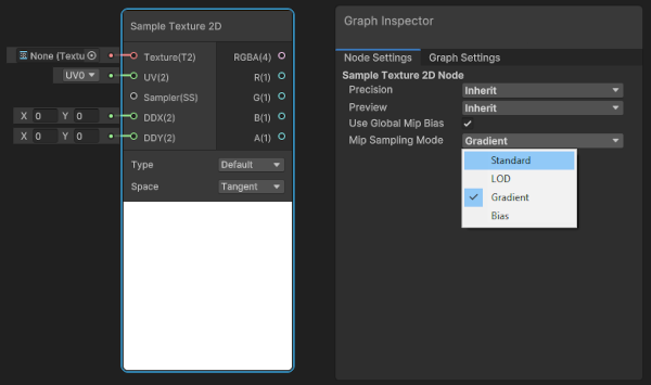
In Unity 2022.2+ can also now handle this all in graph by using the “Gradient” Mip Sampling Mode under the Node Settings on the Sample Texture 2D node itself, to expose derivative inputs. Use the DDX and DDY nodes on some continous UV coordinates when connecting to these ports.
In order to get shadows working in an Unlit Graph you need to add some important keywords which allow the ShaderLibrary to calculate shadow info.
I’ve shared a Custom Lighting for Shader Graph package on github, which can handle this for you. For supporting shadows, use the Main Light Shadows and Additional Lights subgraphs. Both of these will work in Unlit Graphs.
Main Light Shadows
If you’d instead prefer to handle it yourself, Create these Boolean Keywords in the Shader Graph Blackboard :
_MAIN_LIGHT_SHADOWS- Required to calculate shadows_MAIN_LIGHT_SHADOWS_CASCADE- Required to obtain correct shadows when using cascades > 1_SHADOWS_SOFT- Adds support for the Soft Shadows option
Make sure you set the Reference field, and not just the name. Also set them to Multi Compile and Global, and untick Exposed.
Can then sample shadows by calculating the shadowCoord :
float4 shadowCoord = TransformWorldToShadowCoord(positionWS);
Then use one of the following :
Light light = GetMainLight(shadowCoord);andlight.shadowAttenuationto obtain the shadows.- also equivalent to :
float shadowAtten = MainLightRealtimeShadow(shadowCoord);
- also equivalent to :
- (v11+ / 2021.1+)
Light light = GetMainLight(shadowCoord, positionWS, shadowMask), which additionally allows supporting the “ShadowMask” baked GI mode. You would typically passSAMPLE_SHADOWMASK(lightmapUV)into theshadowMaskparameter.- also equivalent to :
float shadowAtten = MainLightShadow(shadowCoord, positionWS, shadowMask, _MainLightOcclusionProbes);
- also equivalent to :
Additional Light Shadows
For additional lights, you need the following keywords:
_ADDITIONAL_LIGHT_SHADOWS- Required to calculate shadows_ADDITIONAL_LIGHTS- Required to prevent the other keyword being stripped from builds
In your light loop, you’d then use :
- (v8 to v10)
Light light = GetAdditionalLight(i, positionWS);, again withlight.shadowAttenuationto obtain shadows. - (v11+ / 2021.1+)
Light light = GetAdditionalLight(i, positionWS, shadowMask);. The shadowMask parameter here can either be set to the sameSAMPLE_SHADOWMASK(lightmapUV)variable, or can usehalf4(1,1,1,1)if you don’t require supporting it. You still need to specify the parameter for the function to calculate shadows.
For better examples see CustomLighting.hlsl in my Custom Lighting package. Also see the Lighting.hlsl, RealtimeLights.hlsl (v12+) and Shadows.hlsl files in the URP ShaderLibrary. Can find these under the Packages in the Project window, or via Unity/Graphics github.
You can disable fog entirely via Unity’s Lighting window (under Environement tab). If you still want fog enabled, but a certain object to not include fog, you can disable fog in a Lit Graph by using a Custom Function node.
I’d recommend using String mode, with a Vector4 Input named “In” and a Vector4 Output named “Out”. The function name can be anything (e.g. DisableFog), while the body should use :
For URP Target :
|
|
The function itself doesn’t do anything, except pass the input straight through. But by using the #define we override the later MixFog function call (in URP/PBRForwardPass.hlsl), so rather than applying fog it just outputs the unmodified colour.
For Built-in Target :
|
|
For the Built-in version, they are already using the UNITY_APPLY_FOG macro (in SG/Built-in/PBRForwardPass.hlsl), so we undefine and then redefine it to output the colour (second parameter).
This is kinda hacky (abusing what macros are supposed to be used for), but hey it works!~
As of 2023.2, Shader Graph has a “Canvas” material type to create shaders compatible with UI components. See Roadmap
For previous versions :
Shader Graph does not have proper support for UI, however it is possible to still use it with some workarounds & drawbacks. This is written with URP in mind, but it may work the similar in other pipelines.
- Use the Unlit Graph, or Sprite Unlit Graph. UI should not use Lit or other graph types.
- For Image component, use a Texture2D property with
_MainTexname/reference to obtain the texture. - Avoid using
Screenspace-Overlaymode on the Canvas - Graphs won’t work with UI Masking (e.g. Scroll Rect/View component) and causes warnings about not having correct Stencil properties.
More detailed info/setup below
Canvas
The Canvas can’t use Screenspace-Overlay mode with Shader Graphs, as that renders all shader passes generated by the graph (such as Shadowcaster / DepthOnly / DepthNormals / etc). Unless you edit the generated code (explained more in the section below), we must instead use Screenspace-Camera mode (and set camera field). Worldspace UI also works.
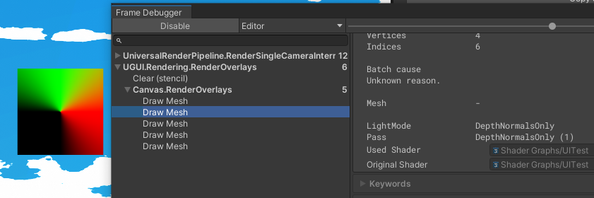
UI Image rendering incorrectly on a Screenspace-Overlay Canvas. As you can see from the Frame Debugger, it’s rendering 5 times with each pass (such as the selected DepthNormalsOnly pass)
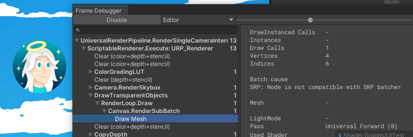
UI Image rendering correctly on a Screenspace-Camera Canvas
If you don’t want Post Processing to affect the UI, can create an Overlay Camera with the Culling Mask set to UI and Post Processing off :
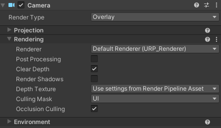
Then set the Screenspace-Camera Canvas to use that new camera and add it to the Stack on the Main Camera.
Masking
Graphs will cause the UI to not work with masking, such as the Scroll Rect/View and Mask components. This requires Stencil operations, which shader graph does not support/expose.
The RenderObjects feature can override Stencil operations, however we cannot use it here for a few reasons :
- It seems the Layer that UI GameObjects are on is ignored, only the layer of the Canvas is important. So it doesn’t actually filter correctly, without nesting a Canvas in the Scrollview Viewport.
- Even if we do that, using a feature also moves rendering the object out of the regular Transparent queue. The mask already renders and is cleared before the feature executes.
If you don’t need masking, but want to surpress warnings like “Material UI doesn’t have _Stencil property” you can create Float properties in the Blackboard with those names (_Stencil, _StencilComp, _StencilOp, _StencilWriteMask, _StencilReadMask, _ColorMask), however it is not possible to make them actually do anything from the graph.
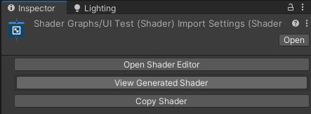
If you require masking to work, you will need to copy the shader code generated by the graph and edit it. This would involve clicking the “View Generated Shader” button in the inspector when viewing the Shader Graph asset. Save the shader that appears in your assets, and use that on Materials instead of the graph.
To actually support the masking, add the following Properties and edit the SubShader :
Shader "Shader Graphs/UITest" {
    Properties {
        // ... (properties generated by graph)
        _StencilComp ("Stencil Comparison", Float) = 8
        _Stencil ("Stencil ID", Float) = 0
        _StencilOp ("Stencil Operation", Float) = 0
        _StencilWriteMask ("Stencil Write Mask", Float) = 255
        _StencilReadMask ("Stencil Read Mask", Float) = 255
        _ColorMask ("Color Mask", Float) = 15
    }
    SubShader {
        Stencil {
            Ref [_Stencil]
            Comp [_StencilComp]
            Pass [_StencilOp]
            ReadMask [_StencilReadMask]
            WriteMask [_StencilWriteMask]
        }
        ColorMask [_ColorMask]
        // ... rest of shader (Tags, Pass, etc)
Note the generated shader code may have multiple SubShaders, you would want to add this Stencil block (and ColorMask) to both.
With the material using this shader, the Image is now masked correctly :

You could also delete all passes except the UniversalForward, and use ZTest [unity_GUIZTestMode] (replacing the ZTest line in the Pass) to support rendering into a ScreenSpace-Overlay UI. All these changes are based on the Built-in RP / UI-Default.shader.
Note that the shader is now completely separate from the graph. If you want to make changes to the graph, you’ll need to regenerate the code and make these changes again. Provided you don’t need to make changes often, it isn’t that bad.
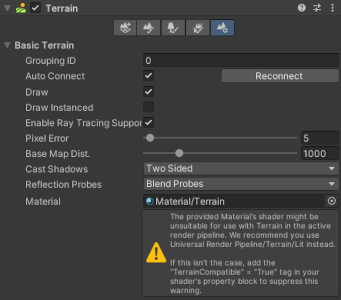
Shader Graph does not have proper support for Terrain, but it is still possible with some drawbacks. (Note this is for regular Draw mode, not Instanced Draw)
A Material can be assigned in the last tab on the Terrain component (cog symbol). When using a material with a graph shader, it will always display a warning that it “might be unsuitable”, but this can be ignored. It’s not possible to remove this warning afaik (without generating shader code from the graph), as we can’t add the TerrainCompatible tag from within the graph editor.
If you want to support painting of Terrain Layers, it is only possible to support 4 layers from a graph. You just need to use specific names/references. At it’s simplest, you’d want :
_Control(Texture2D) : Terrain splatmap. By default is red everywhere, but as you paint other layers it swaps to green/blue/alpha. Each channel represents the layer painted._Splat0,_Splat1,_Splat2,_Splat3(Texture2D) : Albedo/Diffuse textures for each layer. For 2021.2+ make sure “Use Tiling And Offset” is enabled on these texture properties! For versions older, create Vector4_STproperties and use a subgraph as shown in this tweet.- With the URP/TerrainLit shader, the alpha channel of these textures is also used as a Smoothness source. It’s up to you if you’d include that in your calculations.
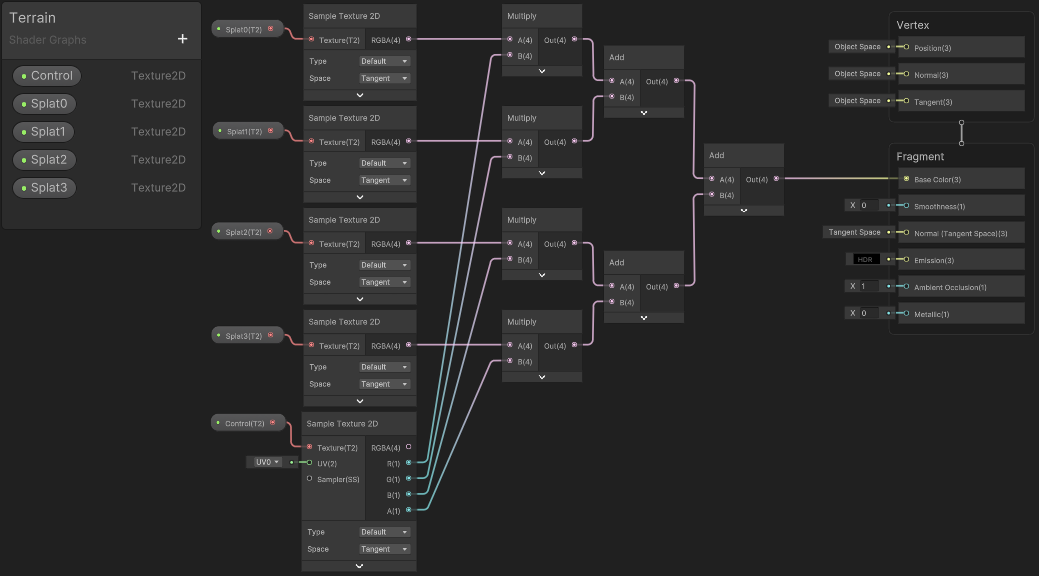
(Click image to view fullscreen)
Layers also provide additional data which the shader could support, such as :
_Smoothness0,_Smoothness1,_Smoothness2,_Smoothness3(Float) : Smoothness floats for each layer. Is typically multiplied with the alpha from the Albedo/Diffuse._Metallic0,_Metallic1,_Metallic2,_Metallic3(Float) : Metallic floats for each layer_Normal0,_Normal1,_Normal2,_Normal3(Texture2D) : Normal/Bump textures for each layer_Mask0,_Mask1,_Mask2,_Mask3(Texture2D) : “Mask” textures for each layer- It’s up to the shader how this is used, but with URP/TerrainLit :
- R = Metallic
- G = Occlusion
- B = Height (for height-based blending)
- A = Smoothness (overrides the albedo alpha &
_SmoothnessNvalues)
- It’s up to the shader how this is used, but with URP/TerrainLit :
- For a full list of properties, see TerrainLitInput.hlsl. Also see TerrainLitPasses.hlsl to see how they are used.
You’d handle these using the same sort of setup and connect to the appropiate ports on the Master Stack (if using a Lit Graph this would involve Smoothness, Metallic, Normal Vector (Tangent) & Ambient Occlusion).
If using Unlit Graph instead (with a Custom Lighting model, e.g. Toon Shaded), you’d Transform the calculated normal from Tangent to World space so it can be used in lighting calculations.
GPU Instancing is typically not required when using MeshRenderer and SkinnedMeshRenderers in URP, as these already use the SRP Batcher to optimise setup between draw calls. When using the SRP Batcher you should avoid using Material Property Blocks though and stick to multiple Materials (or instaniate materials, e.g. using renderer.material)
But if you wish to render lots (many thousands) of the same mesh, you could consider using GPU Instancing via Graphics.DrawMeshInstanced, to remove some of the overhead of GameObjects. Or even better, DrawMeshInstancedIndirect (see answer below instead).
To support DrawMeshInstanced, Materials should already have a “Enable GPU Instancing” tickbox which can be ticked.
However using any properties in the Shader Graph Blackboard will still break instancing. Instead, I’ve found that you can use a Custom Function to define the instancing buffer & properties. This is using macros similar to how you would set up instancing in a code-written shader.
|
|
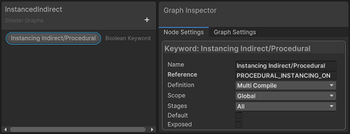
For supporting DrawMeshInstancedIndirect, (possibly also DrawProcedural), add a Boolean Keyword to the Blackboard, with reference set to PROCEDURAL_INSTANCING_ON. Should also be Global and using Multi-Compile.
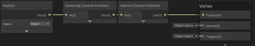
Use two Custom Function nodes. Both with a Vector3 input named “In” and a Vector3 output named “Out”.
- The first uses File mode with the Function Name “Instancing”, to attach the include file (see Shader Graph gist below as an example).
- The second must use String mode with the following :
|
|
(vertInstancingSetup being a function in the include file)
Both functions here don’t alter the input passed in, but it is required to be able to connect the node to the Master Stack. We should connect it somewhere in the Vertex stage - likely easiest using the Position port with the Position node set to Object space (or swap this out for a displaced vertex position if you require that)
See instanced grass example here :
- Twitter Thread : https://twitter.com/Cyanilux/status/1396848736022802435
- Shader Graph Include : https://gist.github.com/Cyanilux/4046e7bf3725b8f64761bf6cf54a16eb
- C# Script : https://gist.github.com/Cyanilux/e7afdc5c65094bfd0827467f8e4c3c54
The Scene Color node samples a texture containing opaque geometry in the scene, allowing you to obtain the colour of opaque objects behind a transparent shader.
This is useful to produce distortion effects. The default UVs input is the Screen Position node, so you can Add or Subtract to that to distort the view, for example with a noise texture. Can find examples in the following posts :
- Water Shader Breakdown (also attempts to remove distortion of objects infront of the water)
- Forcefield Shader Breakdown
- Crystal Shader Breakdown
- Rain Effects Breakdown : Raindrops on Surfaces (Complex)
Note that the node will only function correctly when using a graph with Surface Mode : Transparent (or manually set RenderQueue to 2501+). See below for pipeline-specific differences.
URP :
- Enable Opaque Texture option under the URP Asset. (May have multiple of those assets for each quality setting)
- Also make sure dropdown on Camera isn’t set to force the Opaque Texture off.
Built-in RP (Unity 2021.2+) :
- Add this SceneColorSetup script to your Main Camera (and optionally other cameras that need the
_CameraOpaqueTexture)
HDRP :
- HD Scene Color node may be more suitable for this pipeline. Provides exposure setting and different LOD levels.
Shader Graph (Examples / Snippets)
If you want to layer a texture containing an alpha channel onto another texture/colour, you can do so using a Lerp, where the A output from the Sample Texture 2D is connected to the T input. The A input would be the colour of the Base/Background while B input would be the colour of what you want to Layer on top.
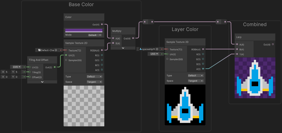
If you don’t have a texture with an alpha channel, you could also use a procedural shape (or a channel from another texture) as the T input. This should be a float value, commonly referred to as a mask.
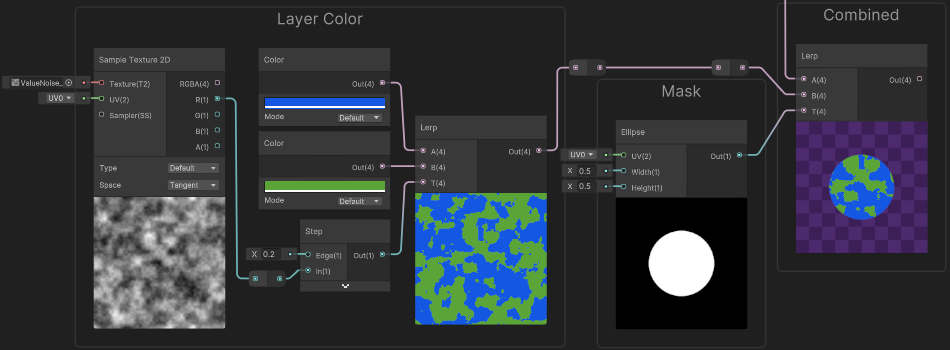
In this case the noise texture is used to interpolate between two colours (blue, green). Then the result is masked using an Ellipse to layer it on the background (same “Base Color” group as used in previous example)
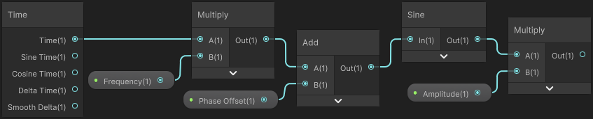
It is not possible to change the frequency/wavelength or adjust the phase of the Sine Time output from the Time node. You can only remap values, such as using a Multiply to adjust the amplitude of the wave.
If you need to control the frequency, use the Time output instead, Multiply by your frequency. To adjust phase use Add or Subtract. You would then put into a Sine node. Can also Multiply again after this to adjust amplitude, same as before.
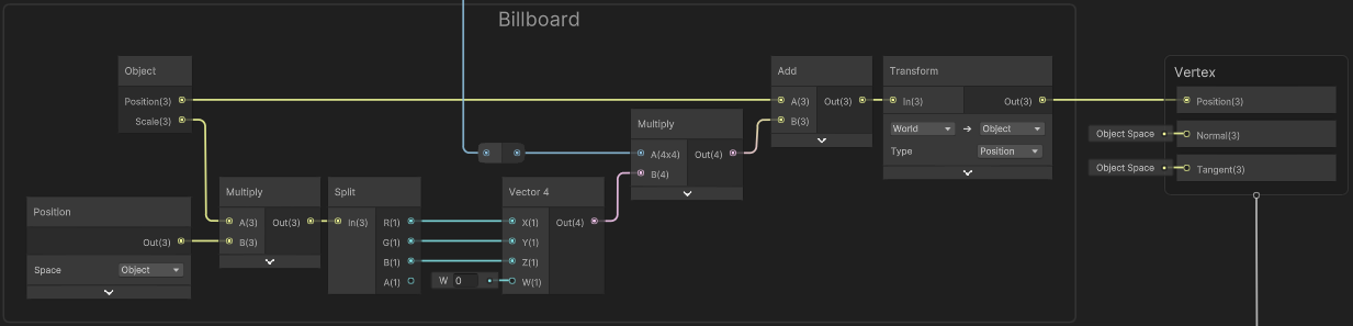
While it’s possible to rotate meshes in C# to produce billboarding (e.g. with transform.LookAt), it’s usually cheaper to handle effects like this in the shader - especially if many objects require billboarding.
Billboarding usually requires the vertex shader to ignore using the view matrix for rotations, but Shader Graph makes it a little trickier to handle as it does space conversions behind the scenes. The Position port in the Master Stack is intended to be in Object space, rather than the clip space output a written vertex shader would usually have. So instead, we need to apply an inverse view matrix to cancel out the rotation Shader Graph applies later.
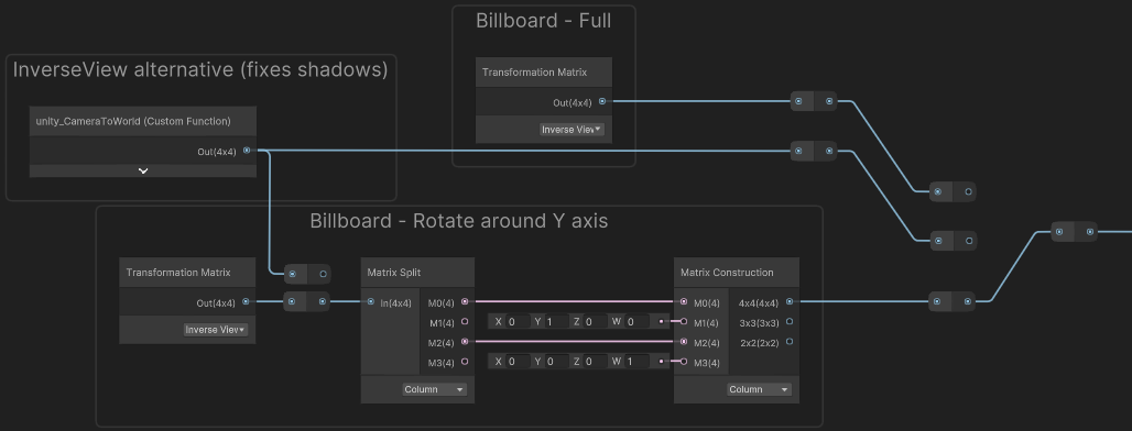
First up, we need a matrix to handle the effect. Can use one of the following.
- Transformation Matrix node set to “Inverse View”
- Custom Function node with Matrix4 output,
Out = unity_CameraToWorld;. This acts the same as the InverseView matrix, but uses the camera even in shadowcasting passes - so shadows will look correct. Should also use set Cast Shadows to “Two Sided” option on the Mesh Renderer.
These may also cause faces to flip too - you can Negate the first column to prevent this (would need Matrix Split and Matrix Construction like shown below), or change the Render Face option in the Graph Settings, e.g. to Both.
To make billboard only rotate around the Y axis, use one of the above (depending if shadows are required) into a Matrix Split (Column mode), and put M0 and M2 into a Matrix Construction node (Column mode). M1 should be set to (0, 1, 0, 0). M3 isn’t too important but can be set it to (0, 0, 0, 1).
Examples :
To apply the scale/rotations from the matrix (without translation parts), can use a 3x3 matrix, or 4x4 matrix and Multiply with Vector4 with W/A component set to 0. (Be sure the matrix is in the A port - the order is important with matrix multiplication!)
Textures are typically applied to the mesh using UV coordinates stored in the vertex data. But we can also use other coordinates.
In a technique usually referred to as “Worldspace Planar Mapping” (sometimes also called “Worldspace Projected UV”), we use the Position node set to World space. This is a Vector3 output but nodes that take a UV port use a Vector2 though, so we first need to Swizzle (or Split and recombine into a Vector2 node), where we can also reorder the components. For example, we can use RB (aka XZ) axis.
- Note that in HDRP, you would use Absolute World space instead, as that pipeline uses Camera Relative Rendering. Using the regular World space would make the texture move with the Camera.
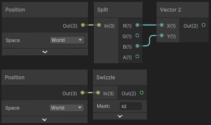
This can then be put into a Sample Texture 2D, or any other nodes that have a UV port - such as procedural noise (Simple Noise and Gradient Noise).
Because we are in World space this acts like projecting the texture from above/below (as the G/Y axis is the one that we didn’t use). The texture will be stretched for any faces that are vertical, but this method is useful for flat surfaces. The texture also does not move, rotate or scale with the object, and so seamlessly continues over neighbouring objects.
We could also project from other axis by using the RG/XY or GB/YZ ports (and swizzle these further for 90 deg rotations).
Sampling from all three axis, then blending based on the Normal Vector is known as Triplanar Mapping. There is a Triplanar node which handles this for you - with only one texture input for all three axis though. For supporting different textures per axis, you’d need to handle it yourself by recreating it in nodes or using a Custom Function. I have a page on my old site explaining this further.
Shader Graph already provides some texture sampling nodes (e.g. Sample Texture 2D) for use in the graph. But it can be useful to sample inside a Custom Function, e.g. inside a loop, or to access sampling macros that don’t have built-in nodes.
Macros
In shader code online you might typically see sampler2D and tex2D() functions being used. This is the older DX9 syntax, but with Shader Graph we mostly use the newer DX11+ syntax which has separate objects for the texture and sampler. This isn’t supported in all platforms though (GLES2), so Unity provides a bunch of macros which can generate different code. These macros are defined in files found under render-pipelines.core/ShaderLibrary/API.
Some important macros for sampling textures are listed below :
-
Sample : Can be used in Fragment stage only
SAMPLE_TEXTURE2D(textureName, samplerName, coord2)SAMPLE_TEXTURECUBE(textureName, samplerName, coord3)SAMPLE_TEXTURE3D(textureName, samplerName, coord3)SAMPLE_TEXTURE2D_ARRAY(textureName, samplerName, coord2, index)SAMPLE_TEXTURECUBE_ARRAY(textureName, samplerName, coord3, index)- These macros would end up using tex.Sample(…) (on DX11+ type platforms)
-
Sample Level (of Detail) : Provides lod input to specify the mip map level sampled. Can be used in both Vertex & Fragment stages
SAMPLE_TEXTURE2D_LOD(textureName, samplerName, coord2, lod)SAMPLE_TEXTURECUBE_LOD(textureName, samplerName, coord3, lod)SAMPLE_TEXTURE3D_LOD(textureName, samplerName, coord3, lod)SAMPLE_TEXTURE2D_ARRAY_LOD(textureName, samplerName, coord2, index, lod)SAMPLE_TEXTURECUBE_ARRAY_LOD(textureName, samplerName, coord3, index, lod)- These macros would end up using tex.SampleLevel(…) (on DX11+ type platforms)
-
Sample Bias : Provides a bias to adjust the mip map level. Can be used in Fragment stage only.
SAMPLE_TEXTURE2D_BIAS(textureName, samplerName, coord2, bias)SAMPLE_TEXTURECUBE_BIAS(textureName, samplerName, coord3, bias)SAMPLE_TEXTURE2D_ARRAY_BIAS(textureName, samplerName, coord2, index, bias)SAMPLE_TEXTURECUBE_ARRAY_BIAS(textureName, samplerName, coord3, index, bias)- Doesn’t seem to be BIAS macros for Texture3D. May be able to use tex.SampleBias(…) function still (or tex3Dbias for GLES2)
-
Sample Gradient : Provides inputs for partial derivatives. Can be used in both Vertex & Fragment stages. (Unless you use
ddx()/ddy()functions to calculate those derivates as those are Fragment only). These are useful when the UV coords used for sampling aren’t continous, see Pixellation along seams question above.SAMPLE_TEXTURE2D_GRAD(textureName, samplerName, coord2, dpdx, dpdy)SAMPLE_TEXTURE2D_ARRAY_GRAD(textureName, samplerName, coord2, index, dpdx, dpdy)- Doesn’t seem there is GRAD macros for other texture types. May be able to use tex.SampleGrad(…) function still (or texCUBEgrad/tex3Dgrad for GLES2)
Shader Graph Texture Types
In Shader Graph v10.3+ (Unity 2020.2.3f1+), structs were added which wrap textures and their associated samplers together, allowing them to both be passed into a Custom Function node in a single parameter. These types are defined in render-pipelines.core/ShaderLibrary/Texture.hlsl
- UnityTexture2D (“Texture 2D” in SG dropdown)
- UnityTexture2DArray (“Texture 2D Array” in SG dropdown)
- UnityTexture3D (“Texture 3D” in SG dropdown)
- UnityTextureCube (“Cubemap” in SG dropdown)
- UnitySamplerState (“Sampler State” in SG dropdown)
The sampler state associated with the texture can be accessed using .samplerstate on the UnityTextureX object. UnityTexture2D also has access to the Texel Size (via .texelSize).
Custom Function Example (v10.3+)
If you aren’t familiar with the Custom Function node syntax see Intro to Shader Graph - Custom Functions and Custom Function docs page.
Here is an example sampling a 3D Texture, using LOD version so it could be used in the vertex stage. This code would be put in a .hlsl file for use with Custom Function File mode. It would also work with String mode but then you would only want the body of the function (inside {}) and you need to match the names for inputs/outputs.
|
|
Inputs :
- “Texture 3D”, named “Tex”
- “Vector2”, named “UV”
Outputs :
- “Vector4”, named “Out”
Custom Function Example (Pre-v10.3)
Earlier versions don’t have these UnityTextureX/UnitySamplerState types so instead need to use the HLSL texture objects, such as Texture3D and SamplerState. For example :
|
|
Inputs :
- “Texture 3D”, named “Tex”
- “SamplerState”, named “SS”
- “Vector2”, named “UV”
Outputs :
- “Vector4”, named “Out”
This could also be used in newer versions, by using the “Bare Texture 3D” and “Bare Sampler State” options on the input/output types. (Though this will likely error in GLES2 platforms, hence why the newer structs were introduced)
Unity supports fixed-size Float and Vector(4) arrays in shaders. We can define them in Shader Graph by using a Custom Function node. In this case, we must use the File mode as the array has to be defined outside the function scope - and this is not possible using String mode.
Here is some example code, defining an array named _ExampleArray, containing 10 floats. Note that the [10] is put after the name, not after float. We can then index the array inside the function, in this case using a loop to add the contents together.
|
|
The array would then be set from a C# script, using :
Shader.SetGlobalFloatArray("_ExampleArray", floatArray);For a Vector4 array, you would use float4 instead of float, and :
Shader.SetGlobalVectorArray("_ExampleArray", vectorArray);When using these C# functions, make sure that floatArray (or vectorArray) has the same length that is specified in the shader! Can pad with zeros if required.
I also have a forcefield shader breakdown which uses an array, if you want a real example.
The following graph can be used to support Fade Mode : “Cross Fade” on the LOD Group component.
This requires using a built-in variable, unity_LODFade. Shader Graph doesn’t provide access to it but we can use a Custom Function node (String mode). Add a single Float output named “Out” and set Body to Out = unity_LODFade.x;. The function’s name isn’t that important but needs to be set to something.
For use with the Dither node, we first need to Absolute to bring any negative values into the positive range. However to make sure it fades in the correct direction, we also need to take the Sign of unity_LODFade.x, and Multiply by the dither result.
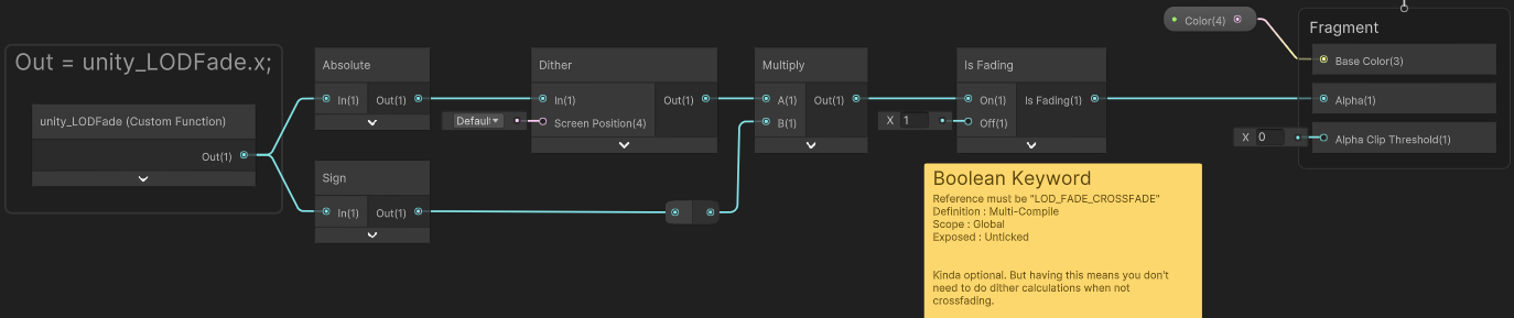
As shown, can then optionally use a Boolean Keyword (set this up in the Blackboard window. While highlighted change it’s settings under the Node Settings tab of Graph Inspector window).
- Name : Is Fading
- Reference :
LOD_FADE_CROSSFADE - Definition : Multi-Compile
- Scope : Global
- Exposed : No / Unticked
Drag the keyword into the graph, then put the result of our Multiply into the On port, and set the Off port to 1.
Using this keyword may be optional, but it means we can avoid having to do the dither calculations when not in the crossfading range. However this would affect batching, so you may want to try it with and without and profile both.
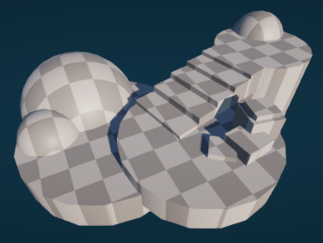
The above graph results in this when moving the camera :

With LOD Group setup looking something like this :
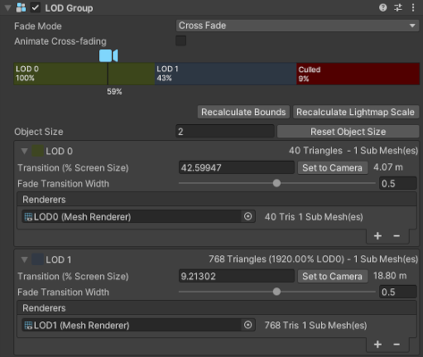
(Usually would have less tris in your higher/further away LODs, but the meshes here is just for example)
For fading based on time, enable Animate Cross-fading. Can control the duration (globally) by setting LODGroup.crossFadeAnimationDuration from a C# script.
For fading based on distance, disable Animate Cross-fading and edit the “Fade Transition Width” values.
See Unity Docs : LOD Group for more info.
For some effects it can be useful to project a texture/noise/etc from screen space (using the Screen Position node into UV ports). When the object or camera moves the texture stays in place relative to the screen, so changes on the model. That isn’t always the desired effect - it could be useful if the texture stayed relative to the object itself.
One easy way to achieve something like this is to use View Space instead, and offset it by the object’s origin in the same space. I do this in my Dissolve Shader Breakdown :
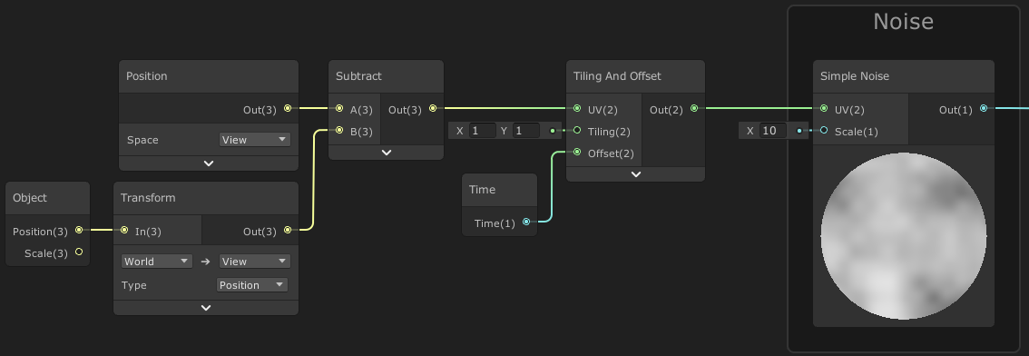
This can create some warping when objects are close to the sides of the camera view, but still tends to work pretty well.
The same thing can be done in screen space (which doesn’t have this warping issue), but the graph is more complicated. It also includes optional groups to deal with screen aspect ratio (so texture/noise isn’t stretched) and make UVs scale down when viewing at a distance :
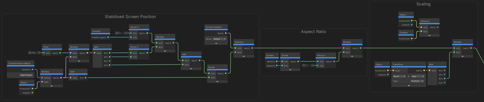
(Click image to view fullscreen)
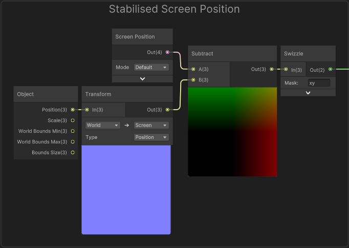
In newer versions of Shader Graph (v14 / Unity 2022.2+) the Transform node now has a Screen option, therefore we can simplify the “Stabilised Screen Position” group in the above graph :
There may be cases where you want to displace/distort a texture in multiple directions. But just using Direction * Time to offset the UV coordinates will mean the difference in values grows larger between where the directions change - tilling and stretching the texture more and more in that gap.
There may be multiple methods to solve this - sampling a texture multiple times with displacements in each cardinal direction and blending between them comes to mind, but that isn’t ideal. The below technique provides a better solution that only uses 2 samples so should also be fairly performant.
The idea is to have the time repeat, by using the Fraction node to only take the decimal part of the value. The displacement will jump back to 0 when time reaches 1, but to avoid seeing this we fade the texture out while fading another version in that uses a different phase (time offset by 0.5).
The fading is controlled by two “triangle waves” using the same repeating time values.
- (Shader Graph technically has a Triangle Wave node built in for calculating that, but it returns a -1 to 1 range while we need 0 to 1. Could use a Remap or Inverse Lerp but I’ve instead calculated the wave myself below, with Multiply by 2, One Minus, Absolute, One Minus)
Here’s an example graph showing the implementation :
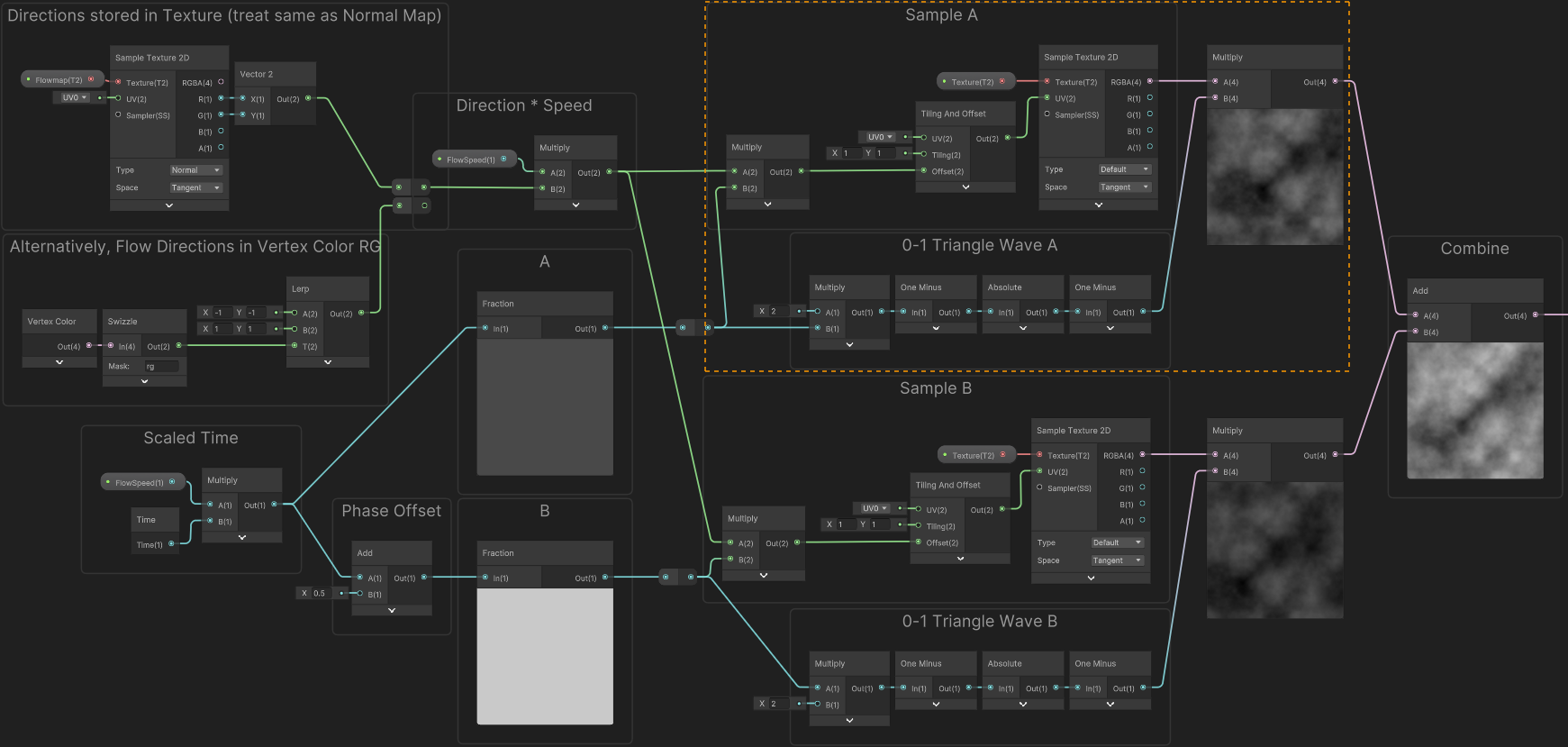
(Click image to view fullscreen)
The section highlighted in orange is the same for both the top and bottom (but with A input swapped for B) so putting this into a SubGraph may help keep the graph more organised.
In the top left, two options are shown for obtaining the displacement directions. Can either use a “Flowmap” - essentially the same as a Normal Map but typically only with RG channels. Should likely still be imported and treated the same as a Normal Map, or at least disable sRGB so colour space differences don’t mess with values. Will also need to remap from the 0 to 1 range of the texture to the -1 to 1 range of direction vectors. I’ve used the “Normal” mode on the Sample Texture 2D to handle this for me.
The other option is storing directions in the mesh data, such as Vertex Color. You may also want a Normalize node after the remapping here. You can then paint the mesh in modelling software like Blender, or in Unity using Polybrush (found in Package Manager), or find a way to set the directions from C#.
In both cases, any values will work but (0.5, 0.5) would be no displacement. (0, 0.5) would be towards the left, (1, 0.5) for right, (0.5, 0) for down, (0.5, 1) for up, etc.
For more details, this “Texture Distortion” CatlikeCoding tutorial should help explain the technique.
Shaders
Shader code can contain multiple passes that define LightMode tags. See here for related docs page which also links to lists of LightMode values used by Built-in & URP.
In the Built-in Render Pipeline, you can also have multiple passes without a LightMode tag (or "LightMode"="Always") which are rendered without lighting/shadows. Unity will render each one as a separate draw call, though the exact render order also depends on the queue :
- In the Opaque queue (Geometry + AlphaTest), all objects render at once using the passes sequentially.
- i.e. All objects render Pass 1, then all objects Pass 2, etc.
- This works with Static Batching (separate batch per pass that is) - though appears to break Dynamic Batching.
- In the Transparent queue, each object renders separately (furthest from camera first) going through the passes sequentially.
- i.e. First object renders Pass 1, Pass 2, etc. Second object renders Pass 1, Pass 2, etc.
- This is likely to avoid blending issues, but also means draw calls will not batch.
In the Universal Render Pipeline, it is possible to have one Pass with "LightMode"="UniversalForward", as well as one pass without (or "LightMode"="SRPDefaultUnlit") and both will render… However this breaks SRP Batcher compatibility for objects using the shader, so is not recommended if the shader will be applied to many objects.
Better options for URP are :
- Use a custom LightMode tag, and tell it to render via a Custom Renderer Feature or RenderObjects feature (put same custom tag value under Shader Tags list)
- Or split passes into two separate shaders & materials, then either :
- Use a RenderObjects feature to re-render objects with an Override Material, filtered to a particular Layer. This works well when dealing with many objects. (If for some reason you can’t use Layers for filtering, there is also a “Rendering Layer Mask” on Renderer component, but would need to write a custom feature to filter using that, as RenderObjects doesn’t include an option for it)
- Apply more Materials to the MeshRenderer. If you go over the submesh count, it’ll render each submesh again. (While this works, I have seen some Unity devs mentioning to not rely on this behaviour. It’s possible this isn’t really intentional so could change in the future)
- Duplicate the object with the Renderer and change it’s Material(s). Parent under the original object to keep them in sync.
Note that in 2022.2+ we also have a Override Shader option on the RenderObjects feature (and in DrawingSettings used with ScriptableRenderContext.DrawRenderers in a custom feature). This will keep using the same property values from the original shader, closer matching Replacement Shaders from BiRP. However, I believe objects rendered with overriden shaders currently do not SRP Batch, so if there is many objects involved it could be expensive. Should try to only use this where required.
Rather than hardcoding ShaderLab operations, it is possible to specify a Property so they can be changed on the material or at runtime (e.g. through material.SetFloat)
// (in Properties)
[Enum(Off, 0, On, 1)] _ZWrite("Z Write", Float) = 1
[Enum(UnityEngine.Rendering.CompareFunction)] _ZTest("ZTest", Float) = 4 // "LessEqual"
[Enum(UnityEngine.Rendering.CullMode)] _Cull ("Cull", Float) = 2 // "Back"
[Enum(UnityEngine.Rendering.ColorWriteMask)] _ColorMask ("ColorMask", Float) = 15 // "RGBA"

[Enum(UnityEngine.Rendering.BlendMode)] _BlendSrc ("Blend Src Factor", Float) = 1 // "One"
[Enum(UnityEngine.Rendering.BlendMode)] _BlendDst ("Blend Dst Factor", Float) = 0 // "Zero"
[Enum(UnityEngine.Rendering.BlendMode)] _BlendSrcA ("Blend Src Factor (Alpha)", Float) = 1 // "One"
[Enum(UnityEngine.Rendering.BlendMode)] _BlendDstA ("Blend Dst Factor (Alpha)", Float) = 0 // "Zero"
[Enum(UnityEngine.Rendering.BlendOp)] _BlendOp ("Blend Op", Float) = 0 // "Add"

[Enum(UnityEngine.Rendering.CompareFunction)] _StencilComp ("Stencil Comparison", Float) = 0 // "Disabled"
[IntRange] _Stencil ("Stencil ID", Range (0, 255)) = 0
[Enum(UnityEngine.Rendering.StencilOp)] _StencilOp ("Stencil Op (Pass)", Float) = 2 // "Replace"
[Enum(UnityEngine.Rendering.StencilOp)] _StencilOpFail ("Stencil Op (Fail)", Float) = 0 // "Keep"
[Enum(UnityEngine.Rendering.StencilOp)] _StencilOpZFail ("Stencil Op (ZFail)", Float) = 0 // "Keep"
_StencilWriteMask ("Stencil Write Mask", Float) = 255
_StencilReadMask ("Stencil Read Mask", Float) = 255

...

// (in SubShader/Pass)
ZWrite [_ZWrite]
ZTest [_ZTest]
Cull [_Cull]
ColorMask [_ColorMask]

//Blend [_BlendSrc] [_BlendDst] // Uses Blend mode for both RGB and Alpha channels
Blend [_BlendSrc] [_BlendDst], [_BlendSrcA] [_BlendDstA] // Use different Blend mode for Alpha
BlendOp [_BlendOp]

Stencil {
    Ref [_Stencil]
    Comp [_StencilComp]
    Pass [_StencilOp]
    Fail [_StencilOpFail]
    ZFail [_StencilOpZFail]
    ReadMask [_StencilReadMask]
    WriteMask [_StencilWriteMask]
}Tangent space uses vectors from the mesh data to stay relative to the surface of the mesh. It can be difficult to visualise for an entire model as unlike other spaces, it can be different per-pixel.
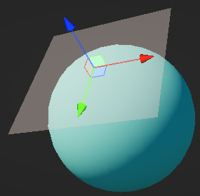
A way to visualise the tangent space for a given point (centered at the gizmo)
The Normal vector you should be familiar with, points out from each vertex - It’s the Z axis of tangent space (shown in blue, since XYZ=RGB). The X and Y axis use the Tangent vector and a Bitangent vector (also called Binormal) - which is typically calculated using a Cross Product with the other two vectors.
These tangent and bitangent vectors are also aligned to the direction of the UV coordinates stored in the mesh. (The tangent follows the X axis of the UV coordinates, and the bitangent follows the Y axis)
The space is needed so tangent space normal maps (that use UV coordinates for sampling) can be converted back to world space to produce correct lighting/shading. The tangent space View Direction is also used to produce Parallax effects.
Of note, if you are using techniques like Triplanar Mapping, then the “Tangent space” you’d need would be different than the Tangent space calculated from mesh data. This article by Ben Golus explains this in detail. In Shader Graph, the Triplanar node already takes this into account when using it’s Normal mode (I believe using the “Whiteout Blend” example)
Colors here are passed into vertex colors - data stored in each vertex of the mesh. To obtain this :
- In HLSL, use the
: COLORsemantic in the vertex input struct. - In Shader Graph, use the Vertex Color node.
Also note that Sprite Graphs will already automatically tint the output using this. There will be an option to disable this. Might be in 2023.3 (currently a pre-release as of writing), but otherwise will have to wait for later versions.
For Sprite Renderer, might vary slightly. If instanced, in Built-in RP sprites use a _RendererColor property in the instancing buffer. In newer versions of URP (2023.1+) that has been replaced with unity_SpriteColor, may need to try a Custom Function to access/output that.
The origin of a mesh is (0,0,0) in object space. To calculate this in world space we could use a matrix multiplciation, like float3 originWS = mul(UNITY_MATRIX_M, float4(0,0,0,1)).xyz, however a cheaper method is to extract the translation data from the matrix :
UNITY_MATRIX_M._m03_m13_m23- (or
unity_ObjectToWorld._m03_m13_m23)
This is equivalent to the Position output of the Object node in Shader Graph.
Note : Unity 2023.1+ now uses SRP Batching for sprites (in play mode at least) which somewhat fixes this.
For prior versions (and if SRP batching is disabled) :
To save on drawcalls (and performance), Sprites on the screen that use the same material, are batched so they can be drawn together. It shows as “Draw Dynamic” in the Frame Debugger window. When this batching occurs, meshes for each sprite are transformed into World space and combined into a single object. The model matrix (UNITY_MATRIX_M) is cleared to an identity matrix (scale of 1, no rotation/translation)
The model matrix is usually responsible for transforming vertex data stored in the mesh into World space, but an identity matrix is used so the values aren’t altered. “Object space” now doesn’t really exist on the shader side, as the vertex positions are already stored in World space.
Anything else that relies on the model matrix also won’t work correctly, such as calculating the origin and scale of the object (outputs on the Object node)
There isn’t really a good way around this afaik, but I don’t work in 2D that often. You could break batching by using different material instances, but that may not be good for performance. Typically you would try to rely on UV coordinates rather than vertex positions.
You could consider using MeshRenderers instead as they can support the SRP Batcher - which doesn’t combine meshes, but instead batches setup between the draw calls.
This error means the shader is using more than 16 samplers. While shaders can support more textures (DX11 supports 128), it has a much lower limit to the number of samplers. To get around this, we can re-use samplers from other textures or use inline sampler states.
- Note this requires using the DX11-style syntax where samplers are separated from textures (e.g.
Texture2DandSamplerState, rather thansampler2D). - Can find more information on the SL-SamplerStates docs page.
In Shader Graph, can use Sampler State node to achieve this, which would be connected to the sampler port on the Sample Texture 2D node.
Be aware that the GLSL mod function is not an exact equivalent to fmod function in HLSL, the result will be different when dealing with negative values.
- HLSL fmod is equivalent to
x - y * trunc(x/y) - GLSL mod is equivalent to
x - y * floor(x/y))
If you are converting a shader, you may want to implement your own mod function using that code instead.
While many shaders in the Built-in RP use CGPROGRAM and ENDCG in their shader code, they are still actually written (and compiled) using HLSL. Unity used to use Nvidia’s CG language, but it was deprecated and is no longer used.
When using the CGPROGRAM tag, Unity automatically includes some files from the Built-in RP shader includes (such as HLSLSupport.cginc and UnityShaderVariables.cginc). This can cause conflicts with other shader libraries - so shaders written for the Post Processing package, URP, and HDRP, should all use HLSLPROGRAM and ENDHLSL instead.
Even if it is all HLSL, it’s important to note that the code written for each pipeline can still vary quite a lot as they use separate include files, which can contain different functions and macros. Can view the ShaderLibrary code via :
- For Built-in RP, can view via this unofficial Github repo, or download it from Unity’s site (Select “Built-in Shaders” option from a dropdown for the version you are using)
- SRP (Scriptable Render Pipeline) core - Accessible to URP, HDRP and custom SRPs.
- URP - Also see my Writing Shader Code for URP post.
- HDRP