Crystal Shader Breakdown

Intro
This post goes over an unlit crystal shader which includes a colour gradient based on the vertical axis (Y) of the object space position and samples the camera’s opaque texture with an offset to fake refraction. A Fresnel effect is also used for opacity so edges are less transparent and will glow more when bloom post processing is also used.
Notes
- This is an Unlit shader using Transparent surface mode and Alpha blending. However the alpha will be left at 1 as we are using the Scene Color node to fake refractions. For URP you’ll need to enable the Opaque Texture on the URP Asset. For information about this node in other pipelines, see FAQ : Scene Color node info
- The gif above is also using point lights in the scene so the walls/floor are illuminated by the crystals. The crystals themselves are not producing the light and is also not affected by them, except for what appears on the camera opaque texture.
- The gif also contains some additional post processing, including Bloom and ACES Tonemapping. See this twitter post for full settings.
Breakdown
Colour Gradient
First up, the shader uses two colours and interpolates between them based on the vertical (Y) axis of the position. I was originally using World space for this as I thought higher crystals being a different colour than lower ones would be interesting. However I found that this limits the level design somewhat as the level has to stay within those Y bounds to show off the whole gradient properly. I switched to using Object space instead, so the gradient/colours stays fixed to the mesh.
For linear interpolation we use the Lerp node and set the A and B inputs to two Color nodes or properties. (For handling more colours, we could alternatively use a Sample Gradient or Sample Texture 2D).
For the T input, since we want it based on the Y position of the fragment/pixel we’ll create a Position node set to Object space and Split it. The G port corresponds to the Y axis. We’ll first put this into the T axis on an Inverse Lerp node then Saturate the result (clamps between 0 and 1) and put it into the T input on the Lerp.
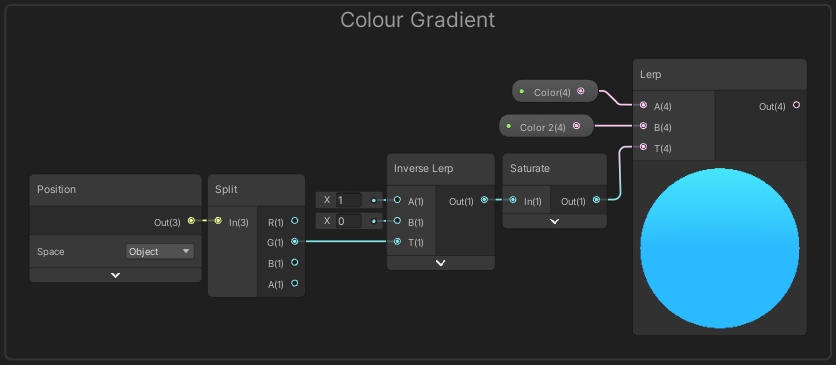
The Inverse Lerp allows us to remap the Y coordinate. I’m setting the A and B inputs to 1 and 0, which currently means the result is the same as a One Minus node, but having this gives the freedom to change what Y coordinate the gradient will start and end at. Also remember since this is in Object space, these values will be relative to the GameObject’s position, rotation and scale.
There’s also a Remap node which I’ll mention quickly as you might ask why I’m not using that here to remap instead. Remap is actually the same as an Inverse Lerp node directly into the T of a Lerp node. The input min/max is the A and B on the first node while the output min/max is the A and B ports on the other. All Vector1s/Floats that is.
In this case, the output min/max is needed in a 0-1 range and a Lerp with those inputs will return the same value of T. It would just be an unnecessary calculation to have that Lerp part too. Remap only needs to be used if the output isn’t in a 0-1 range. (Similarly, if the input was already in a 0-1 range and a different output range was required we could use a Lerp instead of a Remap)
Refraction
Next we’ll handle the refraction part of the shader. This involves offsetting the position used to sample the camera’s Opaque Texture (which needs to be enabled on the URP Asset if you haven’t done so already, see notes section above).
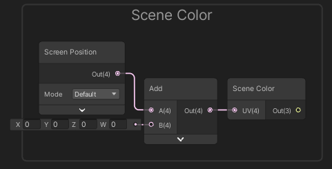
We’ll create a Scene Color node which samples this camera opaque texture. The input needs to be the Screen Position node (which is what it defaults to if left blank), however since we want to offset this we’ll need an Add node too. We’ll leave the second input on this blank for now.
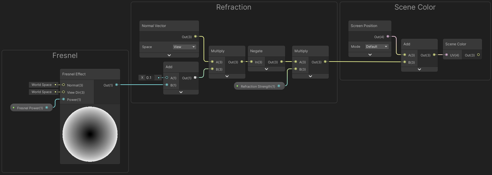
I’m unsure on the most realistic method to handle the refraction here, but for this shader I used the Normal Vector in View space. This allows geometry facing away from the camera to have a higher offset value (on X and Y axis). Geometry facing the camera will have a much lower X and Y amount and while it’ll have a Z coordinate it can be ignored here as the Opaque Texture is 2D.
I also reduced the strength of the offset based on a Fresnel Effect, which would help keep the offset very small for geometry facing the camera. I didn’t want the offset to be completely 0 when the face is perfectly aligned with the camera, so added a small (0.1) amount before multiplying.
Since the normal vector is normalised it’ll have a maximum offset strength of 1, which is quite large for offsetting UVs which are only a 0-1 range. While the Fresnel Effect will help, To reduce the strength further I’m also multiplying by a Vector1 property named “Refraction Strength”, so it can be controlled from the material inspector. A value of 0.4 seemed to work quite well.
I also have used a Negate node here to flip the direction that the offset occurs in.
Opacity
We’re almost done, but we need to combine the Scene Color result and Colour Gradient. I felt the best way to handle this is to have the crystal fairly transparent for faces facing the camera, but facing away would show the colour gradient more.
This is another interpolation, so will involve a Lerp node and since we want to control it based on geometry facing the camera we’ll reuse the Fresnel Efect result from earlier. So we can tweak it a bit, We’ll first Multiply the result by a Vector1 “Fresnel Strength” property, Add a Vector1 “Opacity” property and Saturate it before putting it into the T on the Lerp.
The A input on the Lerp will be set to the Scene Color result, and the B input is set to the result of the Colour Gradient section.
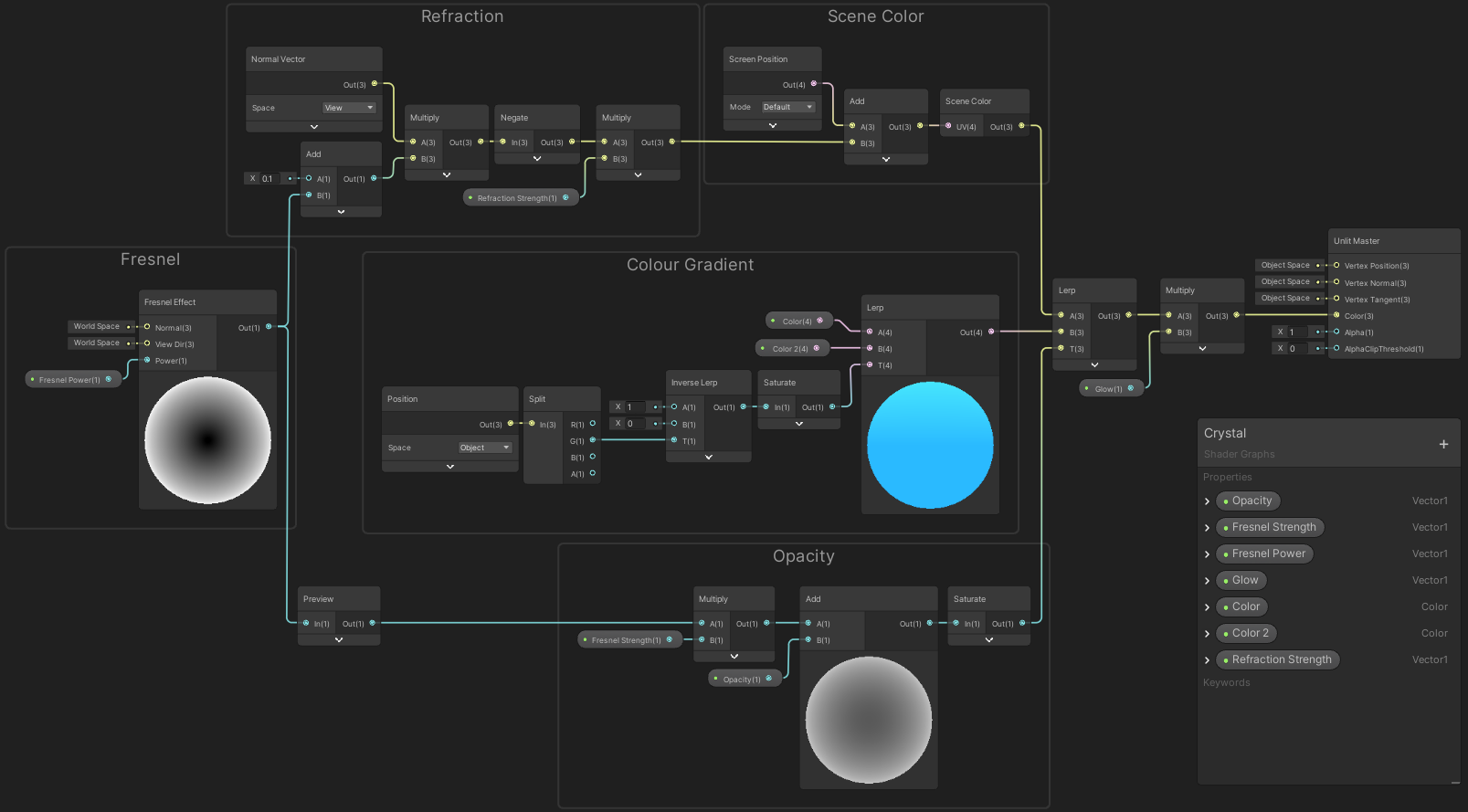
(Click to show full image in new tab)
Finally, I’ve also added a Multiply by a Vector1 “Glow” property before putting the result into the Color input on the Master node as shown above. (Base Color on Master Stack (Fragment) if using URP v10+).
Set the default value of this property to 1 for “no effect”. The whole effect is unlit, but we can increase the value to make the colour brighter. If we’re using HDR colour mode (on the URP Asset) and Bloom in the Post Processing Volume it’ll make it appear to glow. For actually affecting the scene we would need to use Point Lights though.
Other Additions
While not full examples, during writing I also thought of things that could be added :
- Distort Refractions
- For crystals that are meant to more “raw” than cut, it would make sense for imperfections to cause a distorted refraction rather than a perfect one. Could achieve this by mixing some additional noise into the refraction (e.g. Multiply a Gradient Noise node by a small value like 0.05, Add to “Refraction” group, likely before the Multiply with the Refraction Strength). Could also use a noise texture instead of generated noise to be able to swap it out for different crystal types. Could also make the noise affect the opacity or colour slightly.
- Parallax Effects, e.g. parallax effects
- Edges
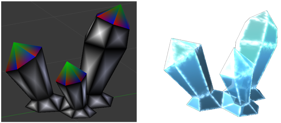
- Some crystal shaders also like to highlight/outline the edges more. This can be achieved by baking gradients into the model’s Vertex Colors (in modelling program, e.g. Blender)
- e.g. Paint quads black and add an additional vertex in each center painted white. For triangular faces, can apply colours of
(1,0,0),(0,1,0)and(0,0,1)to each vertex. - In the shader, would then use Vertex Color node, Split and use two Minimum nodes to combine the RGB channels. Then Smoothstep to remap. Can optionally combine with noise, and Add (or use in T of Lerp) to apply to shader Base Color
Thanks for reading! 😊
If you find this post helpful, please consider sharing it with others / on socials
Donations are also greatly appreciated! 🙏✨
(Keeps this site free from ads and allows me to focus more on tutorials)