Water Shader Breakdown
Intro
This water shader is based on using the camera’s colour and depth textures to create transparent water with distortions/refraction. It also samples Voronoi using UVs of world space coordinates reconstructed from the depth value, to add some water caustics on underwater objects.
Notes
- This is an Unlit shader, applied to a flat plane. Note that everything is rendered to this plane so the camera cannot go underwater or the affect will disappear.
- The water distortion/refraction is based off this Catlike coding tutorial.
- In order to produce nice looking water caustics I’m using a technique I saw in a Brackeys video (Which was based off of this video), but rather than sampling the Voronoi using object UVs, I’m basing it off the X and Z components of world space positions reconstructed from depth.
Breakdown
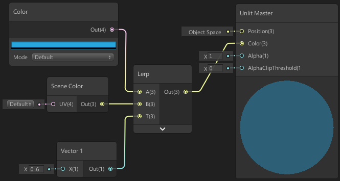
We’ll first create a Scene Color node. This node will allow us to sample a texture of opaque objects the camera renders and we can offset the UVs put into this by some noise to create distortions. For this node to work properly, we need to click the cog on the Master node and set the surface mode to Transparent. You will also need to enable the Opaque Texture (and Depth Texture for later) options on the URP/LWRP Asset. For more information see FAQ : Scene Color node info. Also see Depth for information on the Scene Depth node used later.
So we can add some colour to our water, take the output of the Scene Color node and put it into the B input on a Lerp node. Then create a Color node with a blue/cyan colour and put this into the A input. We can then plug a Vector1 value into the T input in order to control the visibility of our water. I’m using a value of 0.6 for this. You may also want to convert it to a Vector1 property so it can be edited from the material inspector. We’ll put the output of this Lerp into the Color input on the Master node.
If we set up a scene with a plane using this shader, we should see a transparent-looking plane which is slightly tinted blue/cyan. (I say transparent-looking, because we aren’t actually using “alpha” transparency – we’re just using the Scene Color node to render what is behind to the plane itself).
Distortion
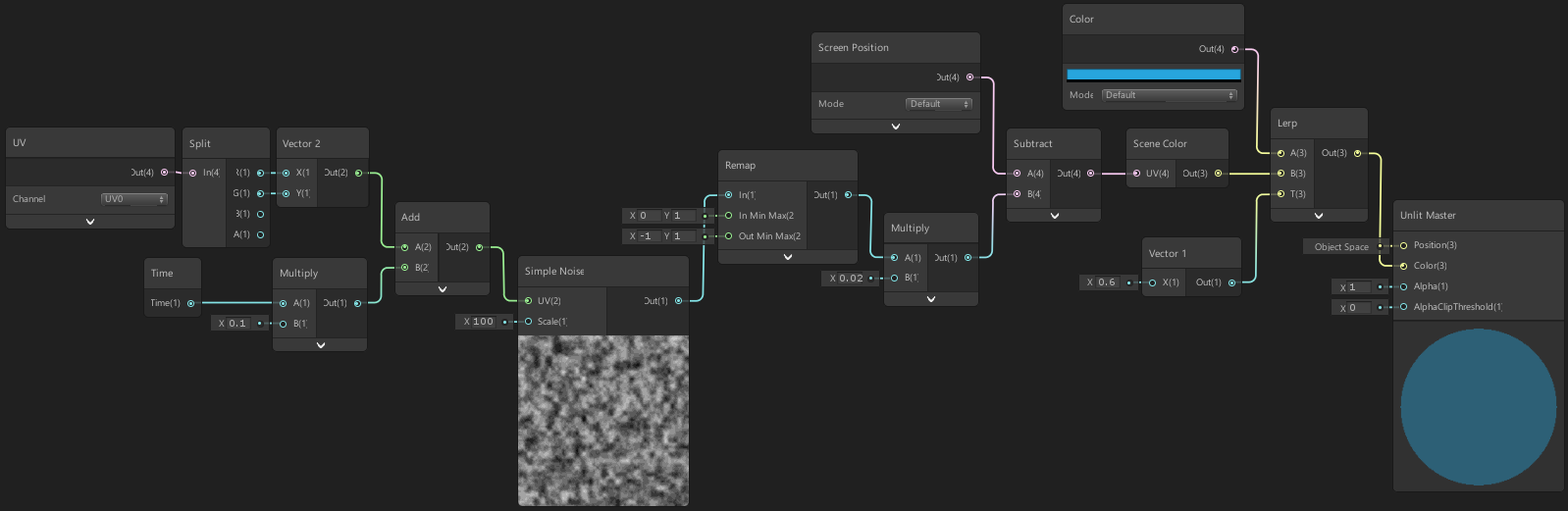
So far this isn’t very impressive, so next we’ll add the distortion/refraction. Currently the Scene Color node uses a default input, which is equal to the output of a Screen Position node. So we can offset the position, we’ll create that node and put it into the A input of a Subtract (or Add, doesn’t really matter which as we’ll be offsetting using noise in a -1 to 1 range). We’ll leave the second input as 0 for now, and put it into the Scene Color node.
We will be using plane’s UVs for the distortion/refraction noise. By doing this, when we look through the water straight down it will be a uniform distortion, but when we look diagonally the noise will be squashed vertically and more distant parts will appear to be distorted more.
Create a UV node, Split the output and put the R and G components into a Vector2. (Note that because we are using UVs, the object scale will affect the distortion. If you don’t want this you can Multiply this by the XZ components of the object’s scale from the Object node).
To animate the distortion we’ll create a Time node, Multiply the Time output by 0.1 then Add the output of this and the output of the Vector2 together. We can use this as the UV input into a Simple Noise node with a Scale input of 100 to generate noise. Put this into a Remap node, with an In Min Max of 0, 1 and Out Min Max of -1, 1, to change the range of the noise. We can Multiply this by a small value such as 0.02, which will control the strength of the offset, and then put this into the second input of the Subtract (or Add) node we created earlier.
Removing distortion on objects above water plane
Now we have some distortion, but you may notice an issue… Opaque objects that are above/in-front of the water plane will also be distorted. In order to fix this we will determine whether our distorted scene pixel is above or below the water’s surface. If it is above, we can just use the undistorted pixel instead. This won’t be a perfect fix, but we have no way of knowing what the pixel colour should be behind those objects.
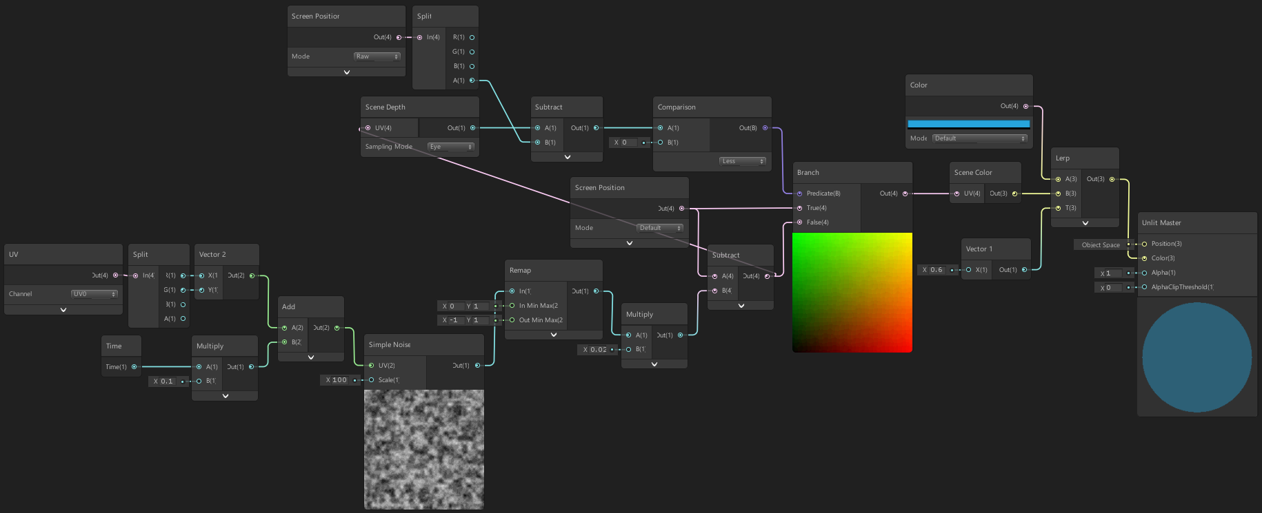
To do this, we need to use the Scene Depth node set to the sampling mode of Eye, using the same UV input as the Scene Color (our distorted screen position). This obtains the linear depth value of scene objects at the distorted pixel in terms of world/view space units.
Next create a Screen Position node set to Raw mode. If we Split it. The W/A component of this is the depth to the fragment / water’s surface. (For info on why can see the Fog Plane Shader Breakdown or Depth post)
We can take the Scene Depth output and Subtract the water surface depth (that W/A component), then put this into a Comparison node with a second input of 0 and mode of Less. (You could also just compare the two depth values directly instead). This returns a Boolean which will be true if the scene depth is smaller than the surface depth, (meaning the scene depth is closer to the camera, aka above the surface).
We’ll plug the boolean into the Predicate input of a Branch node. Then set the True input to a Screen Position node (set to Default mode, not the Raw one) and set the False input to our distorted screen position (from the Subtract). Then replace the UV input of the Scene Color node with the output of this Branch.
Caustics
Next we’ll add the caustics effect. To do this we will use a Voronoi node, with the Cell Density set to 1. This node produces Voronoi noise, (also referred to as Cellular noise and Worley noise). If you want to know how this noise is generated, this Book Of Shaders page has a good explanation, also see my Voronoi post (on my old site).
To animate it, create a Time node and put the Time output into a Multiply with a value of 4, then put this into the Angle Offset input of the Voronoi. We can then take the output and put it into a Power node with a second input of 5. We’ll then Multiply this by 0.5, Add it to the output of our Scene Color node, then replace the B input into the Lerp with the output.
This is the basis of the caustics effect, but rather than having it on the surface of the water, we want it projected onto everything underwater. In order to do this, we’ll reconstruct the world position from the Scene Depth value we sampled earlier and use the X and Z components of the world position as the UVs input for the Voronoi.
In Shader Graph v11 (Unity 2021.1+) the View Direction node is now normalised in all pipelines. We must use the newer View Vector node to achieve the correct result.
(Text in this post has been changed to account for this, but images have not!)
If you are using prior versions of URP, continue using the View Direction.
For HDRP, the graph at the end of the Fog Plane Shader Breakdown may provide a better example.
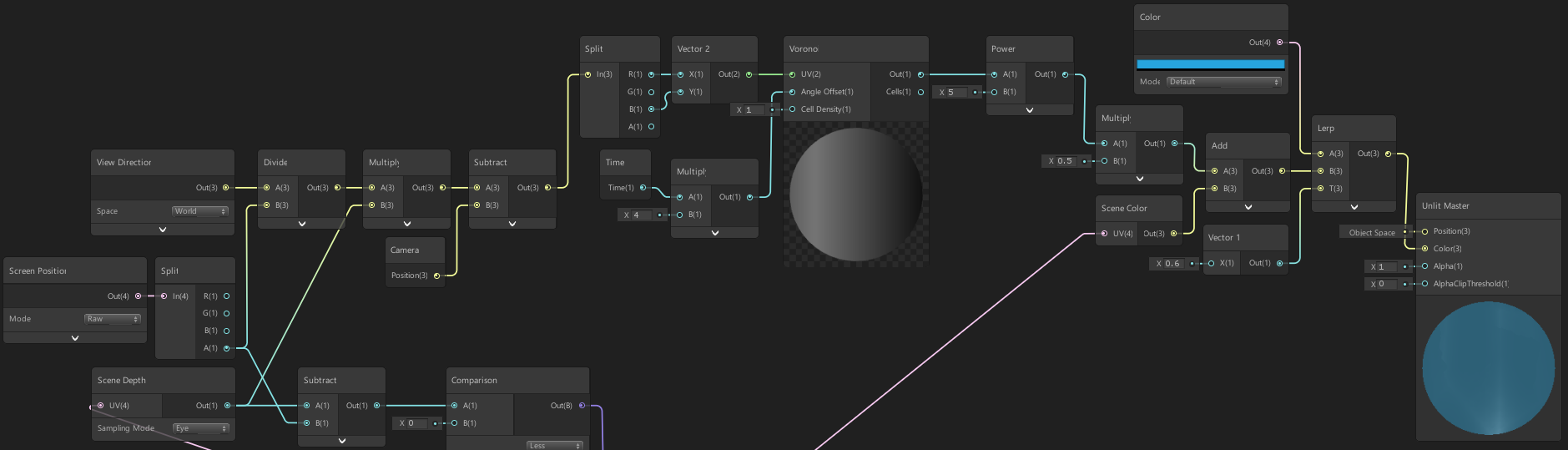
In order to reconstruct the world position from the depth we first need to create a View Vector node set to World space. This obtains a vector from the fragment (aka pixel on the water’s surface) to the camera position. The magnitude of this vector is the distance, but this is not the same as depth. The depth is a distance from the fragment position to a plane that is perpendicular to the camera, not the camera position itself. This creates a triangle as shown in the image.
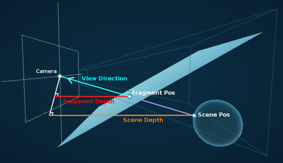
We need to extend this vector to the position in the scene behind the surface. To do this, we Divide the View Vector by the Raw Screen Position W/A depth and then Multiply by the Scene Depth. This works because the scene position we want creates another triangle as shown in the image, and this is the scale factor of that triangle compared to the other.
Currently this position moves with the camera’s position so we now need to Subtract the camera’s world Position from the Camera node to get the actual scene world position. We’ll then Split it, put the X/R and Z/B components into a Vector2 node, then into the UV input on the Voronoi node.
And that’s it! I also originally had a slight gradient applied to the depth at the surface, but I’m leaving the shader here as although it helped show the distortion more, it didn’t entirely make sense to have it and I feel it wasn’t implemented very well.
To improve this water shader further you could try applying a fog by basing the water visibility on the depth, or reconstructed Y pos to make deeper parts darker, as well as add some specular parts to the water surface (e.g. by using the Lit Graph and normal maps. Or Unlit Graph with Custom Lighting)
Thanks for reading! 😊
If you find this post helpful, please consider sharing it with others / on socials
Donations are also greatly appreciated! 🙏✨
(Keeps this site free from ads and allows me to focus more on tutorials)