Depth
Depth is a term used in computer graphics to refer to how far a fragment (a potential pixel) is from the camera. But it can be a bit complicated - as depth can come in different spaces/ranges, vary between platform, and vary between perspective and orthographic camera projections.

(Image showing “Linear01” Depth)
This post goes over everything about depth that I’ve come across (so you could say it’s an in-depth post about depth!), mainly focusing on Unity and the Universal RP (but also includes some High Definition RP stuff). Includes info for both Shader Graph and URP Shader Code (HLSL).
Sections :
- What is Depth?
- Depth Buffer vs Depth Texture
- Shader Depth Output
- Sampling the Depth Texture
- Scene Depth Node
- Depth Difference
- Reconstruct Scene World Position from Depth
What is Depth?
View space, Eye Depth
The easiest type of depth to understand is Eye/View-space Depth which refers to the distance between a position in the scene to a plane perpendicular to the camera’s view - (Not the camera position itself).

The red line corrosponds to the Eye Depth to the Position in the Scene. While the cyan line is the actual Euclidean distance.
During the vertex shader stage, the object space vertex positions in a mesh are converted to World space via the Model Matrix, then to View space via the View Matrix. Here in View space, positions are relative to the camera - which looks down the negative Z axis.
By negating the Z value of a View space position it turns it back into a positive value (assuming the object was infront of the camera), which is the Eye Depth. A depth value of 0 is at the camera’s position, 1 would be 1 unit away, 10 is 10 units, etc. Somewhat oddly, I’ve also heard this depth value referred to as “World” space Depth, likely due to World and View both using the same unit scales - but personally I’d stick to the View or Eye naming.
The ranges of this depth is the same for all platforms. It’s also the same for both othrographic and perspective projections too, since view space is before the projection is applied. You do need to be careful about how the eye depth is obtained though!
In Shader Graph, we can obtain the Fragment’s Eye Depth by either :
- Using the Position node set to View space, Split and Negate the B/Z axis. This works in both Perspective and Orthographic projections.
- Or using the Screen Position node set to Raw mode, Split and take the A/W component. This only works in a Perspective projection though. For Orthographic, A/W is always 1.
I’m unsure if there is any difference in performance between the two for perspective projections. I usually use the second method personally. It’s also a good idea to group the nodes and name them something like “Object/Fragment (Eye) Depth” to keep it similar to the Scene Depth node naming but to make it clear this is the depth to the object/fragment being rendered rather than the scene behind it!

For Shader Code, the first method would be the equivalent of :
// Vertex : (Should work in URP and HDRP?)
float3 positionWS = TransformObjectToWorld(IN.positionOS.xyz);
float3 positionVS = TransformWorldToView(positionWS);
OUT.positionVS = positionVS;
// Fragment :
float fragmentEyeDepth = -IN.positionVS.z;

// Also equivalent to : (even less pipeline specific)
// Vertex :
float3 positionWS = mul(UNITY_MATRIX_M, float4(IN.positionOS.xyz, 1.0)).xyz;
float3 positionVS = mul(UNITY_MATRIX_V, float4(positionWS, 1.0)).xyz;
OUT.positionVS = positionVS;
// Fragment :
float fragmentEyeDepth = -IN.positionVS.z;

// All would require the positionVS being included in the struct passed into the fragment
// using one of the TEXCOORDX semantics, assuming you don't just want the vertex's eye depth.
// Guess you also could just pass that z/depth through rather than the whole view position.
For obtaining the eye depth of objects in the scene (behind the fragment), we would instead sample a special texture that Unity generates for us known as the Depth Texture (aka the Scene Depth node) - but more on that in the later Sampling the Depth Texture and Scene Depth sections.
You will also commonly see Linear01 depth be used, which is just a remapped version of Eye (by dividing by the far plane value). It is still 0 at the camera position, but 1 at the far plane.
Clip space, Normalised Device Coordinates (NDC) & Z Buffer Depth
View space positions also get converted to Clip space via the Projection Matrix. The vertex shader then outputs this position.
Unlike in other spaces, Clip space positions have four components (XYZW) (so are known as “homogeneous coordinates”). In an orthographic projection, the W component is always 1. For perspective projections, it is equivalent to the Eye Depth we discussed in the previous section.
For the XY components, (0,0) would be at the screen center and edges at -W to W. While the Z range depends on the platform / Graphics API :
- Direct3D-like : W at near plane, 0 at far plane
- OpenGL-like : -W at near plane, W plane distance at far plane
These ranges produce the camera’s frustum, which in clip space is shaped as a cuboid (or cube in Open-GL land).
Matrix transformations can’t warp the space in a non-uniform way which is why this fourth component exists. Between the vertex and fragment stages the clip space XYZ is divided by this W component (known as the “perspective divide”) after a bit of additional remapping to convert to 0-1 coordinates across the screen. (Same as the ComputeScreenPos function does, or positionNDC calculated in the VertexPositionInputs struct. In URP these are both found in ShaderVariablesFunctions.hlsl)
// Clip Space Position (calculated for vertex shader SV_POSITION output)
float4 positionCS 	= TransformWorldToHClip(input.positionOS.xyz);
OUT.positionCS 		= positionCS;

// Remap, Handled automatically for the SV_POSITION semantic.
// Note that it's w (eye depth) component remains untouched, even when passed into the fragment.
// Other semantics (TEXCOORDX) passing clip space through would need to do this manually
float4 positionNDC	= positionCS * 0.5f;
positionNDC.xy 		= float2(positionNDC.x, positionNDC.y * _ProjectionParams.x) + positionNDC.w;
positionNDC.zw 		= positionCS.zw;
OUT.positionNDC 	= positionNDC;
// or just
// OUT.positionNDC 	= ComputeScreenPos(positionCS);

// Perspective Divide (handled in Fragment shader)
float3 pd 			= IN.positionNDC.xyz / IN.positionNDC.w;
float2 screenUV 	= pd.xy;
float depth 		= pd.z;
This now gives us Normalised Device Coordinates (NDC), aka a screen position where the XY axis ranges from (0,0) in the bottom left corner and (1,1) in the top right - at least in Unity / URP. This is the same as the Screen Position node in Shader Graph, using it’s Default mode… (though the Z axis doesn’t seem to be passed in when that mode and instead can be obtained by using the Raw mode, Split and handling the Divide Z by W to get the NDC Z/Depth)
Note this depth is non-linear due to changes made by the projection matrix, at least in a perspective projection. This is the value that ends up in the Depth Buffer.
The ranges of this NDC.z / Z Buffer Depth varies depending on the platform :
- Direct3D-like, Reversed Z Buffer : 1 at the near plane, 0 at the far plane
- OpenGL-like, Z Buffer : -1 at the near plane, 1 at the far plane
Can also use the UNITY_NEAR_CLIP_VALUE and UNITY_RAW_FAR_CLIP_VALUE (from com.unity.render-pipelines.core/ShaderLibrary/API) to obtain these near/far plane depth values. If doing calculations on the depth value, these macros may also be useful for remapping to produce a value that is the same across different platforms.
Why Non-Linear?
The reason for making the depth buffer value non-linear (in view space), as well as the Reversed Z Buffer for Direct3D-like platforms, is for better precision. More information about how this works can be found in this NVIDIA article and it can explain it a lot better than I can.
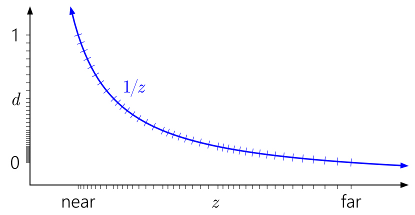
Source : From the NVIDIA article linked below. “The quasi-logarithmic distribution of floating-point somewhat cancels the 1/z nonlinearity, giving us similar precision at the near plane to an integer depth buffer, and vastly improved precision everywhere else. The precision worsens only very slowly as you move farther out.”
Here’s an image to help show the comparison between this non-linear NDC / Z Buffer Depth (labelled “raw” here, as it’s the raw value from the Depth Buffer and Depth Texture), and the Linear01 or Eye depth.

On the right, is the Linear01 value multiplied by 15 (the far plane value) - which is equal to the Eye depth, put through a frac function (aka Fraction node) which makes the value repeat between 0 and 1. Each repeating value of 0-1 on the right is 1 unit. The width of each repeating section gets smaller as it approaches the far plane.
On the left, we have the NDC Depth multiplied by 15 (far plane) and again put through a frac function. While this depth is non-linear in View space, it is actually linear in NDC/Screen space - the width of each repeating section varies based on the viewing angle, but it’s always the same across the plane. I came across this article which again confirms this and notes that it is useful for some hardware optimisations, as well as for post processing - such as comparing the depth value from neighbouring pixels for edge detection.
Roystan has a great edge detection tutorial (for built-in pipeline & PPv2) and Alexander Ameye has a tutorial converting it to work with URP. While I understood the concept that these use, I never realised that having the depth linear in screen space was important here!
Depth Buffer vs Depth Texture
Depth Buffer, ZWrite & ZTest
In the above section I mentioned the Depth Buffer (also referred to as the Z Buffer). When rendering, this buffer is essentially reponsible for sorting pixels/fragments. It ensures that objects closer to the camera will be on-top of objects that are further away (though there are ways to override that behaviour).
Typically only Opaque geometry will write to the depth buffer, controlled by ZWrite in the Shaderlab section of the shader code. Shader Graph will write to the buffer automatically based on the Surface mode (ZWrite On for Opaque, Off for Transparent). If an object doesn’t write to the buffer, other objects can’t test against it later.
Opaque geometry gets rendered front-to-back, meaning objects closer to the camera get drawn first, writing to the camera’s colour and depth buffers. When an object further away tries to render, it tests against the values in the buffer based on ZTest in Shaderlab code. This can’t be changed in Shader Graph, but you can override the values in URP using a RenderObjects feature on the Forward Renderer.
ZTest has a default value of LEqual, meaning if the fragment’s depth is less than, or equal to the value in the depth buffer it will render, otherwise the fragment is discarded/culled. We could instead use ZTest Greater, to only render an object if a closer object has already written to the buffer. e.g. In order to show a silhouette of the object when it is occluded.
By rendering opaque objects closer to the camera first, we don’t have to waste computation on pixels that would be covered by other objects… Technically, depth-testing / ZTest is actually handled after the fragment shader but there is also additional optimisations on GPU hardware that allow an early depth test to take place before the fragment - see the SV_Depth section for more info.
But when rendering Transparent geometry, it instead has to render back-to-front and typically does not write to the depth buffer, in order to achieve the correct alpha blending. The objects are sorted by how close their origin is to the camera, but this can vary a bit as the camera moves, which is why sorting transparent shaders can sometimes be difficult.
Depth Texture
Between rendering objects in these opaque and transparent queues, the Universal RP copies the Depth Buffer and stores it in the Depth Texture. I would assume something similar happens in HDRP.
This then allows Transparent shaders to read that texture and use it in their calculations. e.g. to create intersection effects like in the Simple Forcefield Breakdown or edge-foam for toon water shaders and fog effects like the Fog Plane Shader Breakdown.
Note that other Transparent objects will not show on the Depth Texture, as they do not typically write to the Depth Buffer (ZWrite) and even if they did, the buffer was copied to the texture before transparent objects were even rendered.
For some platforms, they do not support copying the depth buffer - and it also can’t copy if MSAA (multisample anti-aliasing) is enabled on the URP asset currently. This might change in the future though, see the “CanCopyDepth” function at the bottom of the UniversalRenderer class (previously known as ForwardRenderer).
For those cases where the copy cannot occur, a Depth Prepass is used instead. Before anything is rendered, the entire scene is rendered using the DepthOnly pass in the shader. You can see whether the Copy Depth or Depth Prepass is in use via the Frame Debugger Window.
Shader Depth Output
SV_Depth
Fragments usually control their depth from the mesh, based on the interpolated values during rasterisation (between the vertex and fragment shader, turning the geometry into fragments/pixels).
However it is also possible for the fragment shader to override the depth values that will be written into the depth buffer. This can’t be done in Shader Graph, only in HLSL Shader Code. You can likely generate code from the graph and edit it though.
The fragment shader usually outputs colour, using the SV_Target semantic. This can be set up either two ways, either as the usual :
half4 frag (v2f i) : SV_Target {
	... // calculate color
	return color;
}
Or by instead using a struct. This is slightly more flexible as it allows us to also use other output semantics, such as the SV_Depth semantic :
struct FragOut {
    half4 color : SV_Target;
	float depth : SV_Depth;
};

FragOut frag (v2f i) {
	... // calculate color and depth
	FragOut o;
	o.color = color;
	o.depth = depth;
	return o;
}
Here we can now specify a depth value as well as color. As mentioned previously this will override what is written into the depth buffer.
For an Orthographic projection we need to output a linear depth value where 0 is the near plane and 1 is the far plane. But we also need to take into account the reversed depth buffer for Direct3D-like platforms, which is 1 at near and 0 at far instead. We can check if it is reversed by using the UNITY_REVERSED_Z macro. It will be 0 when not reversed, and 1 when reversed.
We can handle this reversed-z by doing the following :
float depth = 1;
// **0** at the near plane, **1** at the far plane
// Using a value of 1, aka the far plane as an example

#if UNITY_REVERSED_Z
	// Reversed, **1** at the near plane, **0** at the far plane
	depth = 1 - depth;
#end
...
o.depth = depth;
For a Perspective projection, we need to convert to a non-linear value - mentioned in the Clip & NDC space, Z Buffer (Raw) Depth section. If we want to set the depth to a specific Eye Depth or Linear01 Depth, we can use the following :
float LinearDepthToNonLinear(float linear01Depth, float4 zBufferParam){
	// Inverse of Linear01Depth
	return (1.0 - (linear01Depth * zBufferParam.y)) / (linear01Depth * zBufferParam.x);
}

float EyeDepthToNonLinear(float eyeDepth, float4 zBufferParam){
	// Inverse of LinearEyeDepth
	return (1.0 - (eyeDepth * zBufferParam.w)) / (eyeDepth * zBufferParam.z);
}

// e.g. The following would be a depth value at the near and far planes.
float nearPlaneDepth = Linear01Depth(0, _ZBufferParams);
float farPlaneDepth = Linear01Depth(1, _ZBufferParams);

float nonLinear = EyeDepthToNonLinear(eyeDepth, _ZBufferParams);
// would also be equal to :
float nonLinear = LinearDepthToNonLinear(eyeDepth / farPlane, _ZBufferParams);
/*
as _ZBufferParams .w is equal to .y/far, and .z equal to .x/far.

Specifically, the values of _ZBufferParams are :
// x = 1-far/near
// y = far/near
// z = x/far
// w = y/far
// or in case of a reversed depth buffer (UNITY_REVERSED_Z is 1) :
// x = -1+far/near
// y = 1
// z = x/far
// w = 1/far
*/
As commented, these functions are the inverse of the Linear01Depth and LinearEyeDepth. They also handle the Direct3D vs OpenGL platform differences for us too, so a UNITY_REVERSED_Z check is not needed when using these.
Note that you shouldn’t use SV_Depth without a good reason, as it turns off early-z/depth testing optimisations on the GPU. This allows the depth to be tested against the depth buffer early, and discard the fragment if it fails, before the fragment shader even runs - since it knows the fragment won’t be visible so there’s no need to calculate it’s colour/shading.
Of course, if the shader is writing to SV_Depth then the fragment has to run, as the depth test needs to occur on this new depth value rather than the old one - Hence why those optimisations would be disabled. This allows the regular depth test to then take place after the fragment shader.
Using Alpha Clipping (clip function) or discard in the shader also turns these optimisations off so the performance would be comparable to that. This is because during the early depth test a value has to also be written to the depth buffer if the test passes, assuming ZWrite is On. The test could pass, write to depth buffer, then the fragment shader could clip/discard - therefore the value written to the depth buffer would have been incorrect.
Opaque shaders that use SV_Depth should also apparently be rendered after other opaque objects (according to this docs page), e.g. during the AlphaTest queue.
Tags { "Queue" = "AlphaTest" }Conservative Depth Output (SV_DepthGreaterEqual, SV_DepthLessEqual)
Similar to SV_Depth, there is also other depth outputs which still allow the early-z optimisations to run. This is known as Conservative Depth Output and involves using either the SV_DepthGreaterEqual semantic or SV_DepthLessEqual. They can be used in the same way as SV_Depth explained above, but has the additional inequality to be aware of.
SV_DepthGreaterEqual allows us to output depth as long as the value it is set to is greater than or equal to the value determined during rasterisation. If the value set is less, it will be clamped to the same value the rasteriser uses. In other words, you can only use it to increase the depth value.
SV_DepthLessEqual is the opposite, where the value set must be less than or equal to the value determined during rasterisation. Again, it will be clamped if the value set is greater. You can only use this semantic to decrease the depth value.
Sampling the Depth Texture
As explained earlier, the depth texture contains depth values of the scene - how far opaque objects are from the camera plane. It should only be used by shaders in the Transparent parts of the Render Queue, specifically 2501 or higher (in URP at least). It allows us to obtain the depth of objects behind our transparent surface. If you instead need the depth to the fragment being rendered, you can calculate that without using the depth texture - see the Eye Depth section.
Sampling the Depth Texture can be done in Shader Graph via the Scene Depth node (see below).
For URP Shader Code (HLSL), include DeclareDepthTexture.hlsl, and use it’s SampleSceneDepth function with the Screen coords to obtain the Raw Depth value. (pass positionNDC (from GetVertexPositionInputs, or use ComputeScreenPos with clip space pos, both in ShaderVariablesFunctions.hlsl) from vertex to fragment, then uv = screenPos.xy / screenPos.w).
Be aware that the Depth Texture needs to be enabled in URP, this will be discussed more in the section below.
e.g.
// (URP Example)
#include "Packages/com.unity.render-pipelines.universal/ShaderLibrary/DeclareDepthTexture.hlsl"
...
// Vertex
float4 positionCS = TransformObjectToHClip(IN.positionOS.xyz);
OUT.positionCS = positionCS;
OUT.screenPos = ComputeScreenPos(positionCS);
...
// Fragment
float rawDepth = SampleSceneDepth(IN.screenPos.xy / IN.screenPos.w);
float sceneEyeDepth = LinearEyeDepth(rawDepth, _ZBufferParams);
For HDRP Shader Code (HLSL), use the SampleCameraDepth function in ShaderVariables.hlsl.
Also, for the Built-in pipeline there is the docs page, also see CameraDepthTexture docs. These explain some macros (specific to the built-in, won’t work in URP/HDRP) and how to enable it for that pipeline.
For converting to other spaces we can use :
- Convert to Linear01 using :
Linear01Depth(rawDepth, _ZBufferParams); - Convert to Eye using :
LinearEyeDepth(rawDepth, _ZBufferParams);
(The built-in pipeline versions of these don’t include the second parameter)
Replacing “rawDepth” with the value sampled from the depth texture (SampleSceneDepth or SampleCameraDepth functions). Bare in mind that these functions are only used with Perspective projections. The Linear01Depth and LinearEyeDepth functions are found in the pipelines.core Common.hlsl.
For Orthographic projections, the rawDepth value is already linear but needs inverting for the reversed z buffer (when _ProjectionParams.x is -1), and lerping it with the near (_ProjectionParams.y) and far (_ProjectionParams.z) clip planes can convert it to view/eye space. Following code is untested but should work :
orthoLinearDepth = _ProjectionParams.x > 0 ? rawDepth : 1-rawDepth;
orthoEyeDepth = lerp(_ProjectionParams.y, _ProjectionParams.z, orthoLinearDepth);
/*
In case you are wondering what these _ProjectionParams values are :
x = 1 or -1 (-1 if projection is flipped)
y = near plane
z = far plane
w = 1/far plane
*/
Scene Depth Node
The Scene Depth node allows us to sample the camera’s Depth Texture. As explained above, this texture contains depth values - how far objects are from the camera plane. It should only be used by shaders in the Transparent parts of the Render Queue, specifically 2501 or higher. Switching the Shader Graph to use a Transparent surface mode will switch it to 3000, but you can also change it manually in the material inspector.
Modes
Perspective Projection
- Raw : Non-Linear value between 0 and 1, directly from the Depth Texture
- Direct3D-like, Reversed-Z : Ranges from 1 at near plane, to 0 at far plane
- OpenGL-like : Ranges from 0 at near plane, to 1 at far plane
- Linear01 : Linear value between 0 and 1.
- Converted using
Linear01Depth(raw, _ZBufferParams); - Ranges from 0 at camera pos, to 1 at far plane
- Converted using
- Eye : Eye (/View space) depth value.
- Converted using
LinearEyeDepth(raw, _ZBufferParams); - Ranges from 0 at camera pos, 1 at 1 unit away, 10 at 10 units away, etc.
- Converted using

Orthographic Projection
In newer versions (tested in 2022.2+) the Raw/Linear01/Eye modes now seem to work properly in orthographic projections (same as perspective), so see above! For exact code used, may want to check generated code or SceneDepthNode.cs.
For older versions :
Click to expand
- Raw : In orthographic, this is a linear value between 0 and 1, directly from the Depth Texture
- Direct3D-like, Reversed-Z : Ranges from 1 at near plane, to 0 at far plane
- OpenGL-like : Ranges from 0 at near plane, to 1 at far plane
- Linear01 : Should not be used in Orthographic, as the Raw value is already Linear!
- Note however that there is still platform differences with this value, see above. If you want a value that will work for both, we need to Branch based on the Z Buffer Sign output from the Camera node, put through a Comparsion node with a B input of 0 and Greater mode. For the True input we can then use the Raw depth value as is, and for the False use the One Minus node on the Raw value. See first part of image below.
- Eye : Should not be used in Orthographic.
- If you want to convert the linear value to eye/viewspace units, use a Lerp with the depth value as the T input, set A to the Near Plane from the Camera node and B to the Far Plane. See image below.

Notes for Universal RP :
- The Depth Texture option needs to be enabled on the URP Asset for the texture to be created.

- Also, strangely in order for the depth texture to be correctly rendered, the “Post Processing” option on the Camera must also be enabled. (Having the Opaque Texture, HDR, or MSAA enabled on the URP Asset also seems to force it to render, but they will have extra overhead). This is true in URP v7.3.1 at least - it is possible that this is a bug and may be fixed in newer versions?
Depth Difference

With the Eye Depth of the Scene (from the above sections) and Fragment (see View Space, Eye Depth section at the beginning of the post), we can use their difference (which means to Subtract them) to achieve some intersection-like effects.
Basically, if both depths are close together, meaning the value is almost the same, then subtracting them will give us a value close to 0. We can take the One Minus of this to only give us the intersection. We also use a Saturate node to clamp the result between 0 and 1.
This method isn’t always accurate however, especially at shallow viewing angles.

Since we are using the Scene Depth, the graph must also be set to use Transparent surface mode for the node to function correctly. Note that this graph also only works in a Perspective projection.
For Orthographic, swap the Scene Depth out for the graph explained in the Scene Depth Node - Orthographic section and swap the Object/Fragment Depth group out for the Position node, View Space, Split and Negate Z/B axis (as explained in the Eye Depth section).
For Shader Code, the above graph would be something like :
// (URP Example, untested but should be the same as the graph above)
#include "Packages/com.unity.render-pipelines.universal/ShaderLibrary/DeclareDepthTexture.hlsl"
...
// Vertex
float3 positionWS = TransformObjectToWorld(IN.positionOS.xyz);
float3 positionVS = TransformWorldToView(positionWS);
float4 positionCS = TransformWorldToHClip(positionWS);
OUT.positionVS = positionVS; // (TEXCOORD1 or whatever, any unused will do)
OUT.positionCS = positionCS; // (SV_POSITION)
OUT.screenPos = ComputeScreenPos(positionCS); // (TEXCOORD2)
...
// Fragment
float fragmentEyeDepth = -IN.positionVS.z;
float rawDepth = SampleSceneDepth(IN.screenPos.xy / IN.screenPos.w);

// For perspective :
float sceneEyeDepth = LinearEyeDepth(rawDepth, _ZBufferParams);
// For orthographic :
//float orthoLinearDepth = _ProjectionParams.x > 0 ? rawDepth : 1-rawDepth;
//float sceneEyeDepth = lerp(_ProjectionParams.y, _ProjectionParams.z, orthoLinearDepth);
/*
In case you are wondering what these _ProjectionParams values are :
x = 1 or -1 (-1 if projection is flipped)
y = near plane
z = far plane
w = 1/far plane
*/

float depthDifferenceExample = 1 - saturate((sceneEyeDepth - fragmentEyeDepth) * 1);
This technique is quite useful for effects such as :
- Intersection, e.g. Simple Forcefield Breakdown
- Edge foam for water shaders
- Fog effects, e.g. Fog Plane Shader Breakdown
Reconstruct World Space Position from Depth
With the fragment’s world position and eye depth values it’s also possible to reconstruct the world position in the scene. The method we can use to do this varies a bit depending on if we’re applying the shader on a mesh in the scene or if the shader is a part of a image effect / fullscreen graph.
Mesh

For explanation, see Fog Plane Shader Breakdown
In Shader Code / HLSL this should be equivalent to :
// (URP Example, untested but should be the same as the graph above)
#include "Packages/com.unity.render-pipelines.universal/ShaderLibrary/DeclareDepthTexture.hlsl"
...
// Vertex
float3 positionWS = TransformObjectToWorld(IN.positionOS.xyz);
float3 positionVS = TransformWorldToView(positionWS);
float4 positionCS = TransformWorldToHClip(positionWS);
OUT.positionVS = positionVS; // (TEXCOORD1 or whatever, any unused will do)
OUT.viewDirVector = _WorldSpaceCameraPos - positionWS; // (TEXCOORD2)
OUT.positionCS = positionCS; // (SV_POSITION)
OUT.screenPos = ComputeScreenPos(positionCS); // (TEXCOORD3)
...
// Fragment
float rawDepth = SampleSceneDepth(IN.screenPos.xy / IN.screenPos.w);
float sceneEyeDepth = LinearEyeDepth(rawDepth, _ZBufferParams);
float fragmentEyeDepth = -IN.positionVS.z; // or abs(IN.positionVS.z)

float3 worldPos = _WorldSpaceCameraPos - ((IN.viewDirVector / fragmentEyeDepth) * sceneEyeDepth);
// try visualising by returning :
return float4(frac(worldPos), 1.0);
Mesh (Orthographic projection)
For versions 2022.2 or newer the above should work in both perspective and orthographic camera projections. But for older versions :
Click to expand

We need to use the Raw mode on the Scene Depth node. The value returned still varies between platforms a bit as explained in the Scene Depth Node - Orthographic section so we need to branch based on the Z Buffer Sign from the Camera node. That gives us a value equivalent to the Linear01 depth, we then need to Lerp between the near and far clip planes to convert it to View/Eye depth.
We can then plug that into the Z axis of a Vector3 node, with the X and Y axis set to the X/R and Y/G outputs from the Position node set to View space, Split. Finally we Transform that from View space to World space.
Since we are using Scene Depth, the Master node should also be set to Transparent Surface mode.

Blit (Perspective projection)
For image effects / blit, the above approaches don’t work as intended as we are rendering a quad to the screen. If you’re working in Shader Code / HLSL, something like keijiro’s DepthInverseProjection might help here. (Note that was written for the Post Processing v2 stack, so may need adapting to work in URP/HDRP)
As for Shader Graph, I have found that the following works but it requires sending in a _InverseView Matrix, (set to cam.cameraToWorldMatrix). The Blit Renderer Feature that I shared on Github has an option for this.
Since we are using the Scene Depth, the graph should also be set to use Transparent surface mode for the node to function correctly, and the blit should occur in the Before Skybox event or any event after.

Left note : Custom Function, Output : “Out” Matrix4x4. Body : Out = unity_CameraInvProjection; Right note : C#, Shader.SetGlobalMatrix("_InverseView", cam.cameraToWorldMatrix); (I’m doing this in the Custom Renderer Feature used to Blit the shader to the screen)
In Shader Graph v12+ (Unity 2021.2+) it is now also possible to add Custom Interpolators.
This could be used to make the graph more performant by moving half of the calculations to the vertex shader - specifically up to the output of the the first matrix multiplication (with the Custom Function)
Blit (Orthographic projection)
This version is very similar to the above but works in an orthographic camera projection. It requires the _InverseView matrix (set to cam.cameraToWorldMatrix). The Blit Renderer Feature that I shared on Github has an option for this.

Custom Function, Output : “Out” Matrix4x4. Body : Out = unity_CameraInvProjection;
In Shader Graph v12+ (Unity 2021.2+) it is now also possible to add Custom Interpolators.
This could be used to make the graph more performant by moving half of the calculations to the vertex shader - specifically up to the output of the the first matrix multiplication (with the Custom Function)
Sources / Additional Info :
- https://developer.nvidia.com/content/depth-precision-visualized
- https://docs.unity3d.com/Manual/SL-PlatformDifferences.html
- https://docs.unity3d.com/Packages/com.unity.shadergraph@8.2/manual/Scene-Depth-Node.html
- http://www.codinglabs.net/article_world_view_projection_matrix.aspx
- https://www.scratchapixel.com/lessons/3d-basic-rendering/perspective-and-orthographic-projection-matrix/projection-matrix-introduction
- https://forum.unity.com/threads/decodedepthnormal-linear01depth-lineareyedepth-explanations.608452/#post-4070806
- https://forum.unity.com/threads/what-is-screenpos-w.616003/#post-4125325
- https://www.khronos.org/opengl/wiki/Early_Fragment_Test
- https://github.com/keijiro/DepthInverseProjection
More tutorials related to depth (for Built-in Pipeline) :
- https://halisavakis.com/shader-bits-camera-depth-texture/
- https://www.ronja-tutorials.com/2018/07/01/postprocessing-depth.html
- https://roystan.net/articles/toon-water.html
- https://roystan.net/articles/outline-shader.html
Thanks for reading! 😊
If you find this post helpful, please consider sharing it with others / on socials
Donations are also greatly appreciated! 🙏✨
(Keeps this site free from ads and allows me to focus more on tutorials)