Fog Plane Shader Breakdown
Intro
This post includes examples to produce fog shader effects. In both cases, the shader is applied to a flat plane or quad where the alpha of the surface is altered based on depth values.
As shown in the screenshot below, it is commonly used to produce vertical fog or used in exits/entrances to fade into white/black (or any other colour). The two fog planes here can be toggled with these tabs to better show the setup/result :


The first example is simpler, but seems to have some inaccuracies at very shallow angles (between the camera’s view direction and plane surface) where the fog can look warped/flattened. The second example is a bit more complex but avoids that issue.
Note that in both examples the camera cannot pass through the quad/plane, or the fog effect will disappear. This effect is intended for third person / top-down / fixed camera angles.
Depth-based effects can sometimes produce different results for Perspective vs Orthographic camera projections. But as of 2022.2+ the shader graphs below should work for both due to changes to the Scene Depth node. The graphs should also work in any render pipeline.
For versions earlier than v11 / Unity 2021.1 be aware that the View Vector node did not exist, but View Direction wasn’t normalised in URP at that time so can be used in its place. For HDRP, Position set to World space → Negate should be equivalent due to the camera-relative rendering.
Notes
- This is an Unlit shader. Transparent surface mode and Alpha blending. May also want to disable Cast Shadows (either in shader for URP/BiRP or via Mesh Renderer component)
- On the Universal Render Pipeline Asset, the Depth Texture option needs to be enabled for the Scene Depth node to work (and make sure it is not overriden on the Camera)
Breakdown
In order to create these fog effects, we need to sample the depth texture from the camera. Shader Graph includes a Scene Depth node which will handle this as well as the conversions into appropiate units for us. By using the Eye sampling mode it will output the “linear depth” in terms of metres/units from the camera plane. If you aren’t familiar with the node, you can read more in the Depth post.
Next we need the depth to the plane (fragment positions) being drawn (in the same space/units), which can be obtained using Position node set to View space. The camera looks down the negative Z axis of this space, therefore to obtain the depth we can Split and use Absolute (or Negate) on the B output (aka Z axis)
(You could alternatively take the alpha/w component of the Screen Position node set to Raw mode - also used in an earlier version of this post. But that only returns the correct value for perspective cameras due to how the projection matrices work. For orthographic it would just be 1 and break the effect)

With both of these to depth values, we can move on to creating the fog plane shaders.
Example 1 (Simple)
We can Subtract the two depth values to obtain the difference in depth between the object’s surface and the scene depth. This produces a value of 0 at the surface, and increasing values the further apart these two depth values are - producing the fog effect.
However before we plug that into the alpha, we can do additional calculations to control the density of the fog by using a Multiply node (or Divide if you prefer to use density values like 2 or 3 instead of 0.5 and 0.33, though dividing may be a slightly more expensive operation than multiplication)
We then need to Saturate to clamp values to be between 0 and 1, as values outside that range can create artifacts with alpha blending and unwanted brightness/glow if bloom post processing is active.

As shown above we can also use a Color property in the Base Color output in the Master Stack, which allows us to adjust the colour of the fog. And can optionally Split to take the alpha component and Multiply it with the saturate output so the fog can be faded by adjusting the colour property.
Example 2 (Accurate)
For a more accurate fog, we can reconstruct world space positions using the depth, which involves using the View Vector node set to World space.
This obtains a vector from the pixel/fragment position to the camera. The magnitude of this vector is the distance between these points, but that is slightly different from depth – which is to a plane that is perpendicular to the camera rather than the camera position itself. This creates the inner triangle in the below diagram :
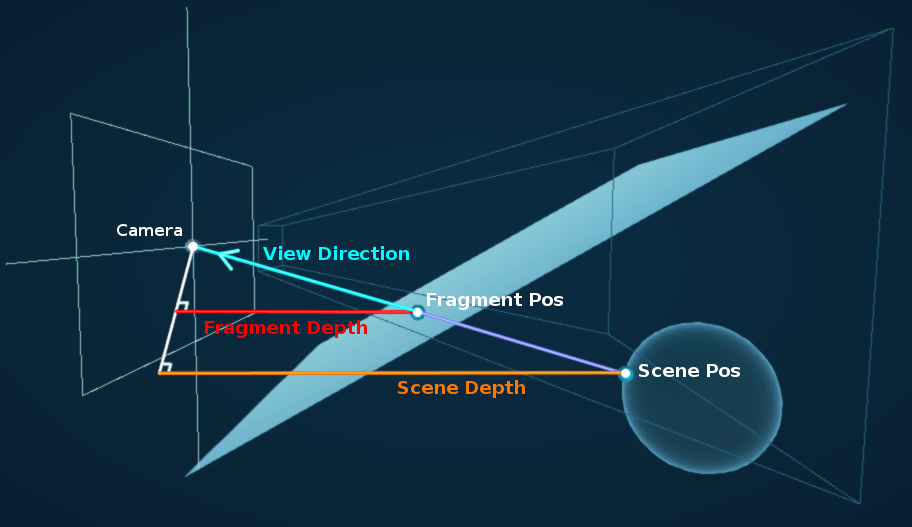
Scene Depth set to Eye mode gives us the depth to the “Scene Pos” (the position we are trying to calculate) creating another triangle (shown larger for this visualisation, but these scene positions may be on either side of the mesh being drawn)
To reconstruct the “Scene Pos” we need to scale the view vector, which can be achieved by dividing the View Vector by the “Fragment Depth” and then multiplying by the Scene Depth.
We can then Subtract this from the camera position, obtained via Position output from the Camera node. (For HDRP this can be skipped due to the camera-relative rendering, could instead just Negate and use World space in the Transform below)

To handle the fog we can Transform our reconstructed positions from Absolute World to Object space, then Dot Product with the Normal Vector also set to Object space. As that vector points outwards from the plane, we also need to Negate the result to make sure the fog is in the correct direction.
A side effect of this method is that scaling the GameObject can affect the density of the fog. If this is unwanted, Multiply by the Scale output from an Object node between the Transform and Dot Product.
And finally, like the earlier example, we can also add a Float property and Multiply (or Divide) to control the density of the fog, must Saturate to avoid artifacts with alpha blending / bloom and can add a Color property to control the colour.

Thanks for reading! 😊
If you find this post helpful, please consider sharing it with others / on socials
Donations are also greatly appreciated! 🙏✨
(Keeps this site free from ads and allows me to focus more on tutorials)