Forcefield Shader Breakdown
Intro
This post is a more advanced version of the Simple Forcefield Breakdown. You don’t have to read that one first, but it might help with understanding this one further. This shader uses a rim / fresnel effect along with the camera’s colour and depth textures to produce a spherical (or hemispherical (dome-shaped)) forcefield (or energy shield) that distorts the view through it, with glowing edges and intersections with objects in the scene. We will also add the ability to produce distortion ripples at points of collision with scene objects, through the use of a custom function.
Notes
- This is an Unlit shader. Transparent surface mode and Alpha blending (but alpha will always be set to 1!)
- If you are looking to make a forcefield without any distortion to visuals – you should follow the simple version instead (linked above).
- The distortion is created using the Scene Color node. For URP you’ll need to enable the Opaque Texture on the URP Asset for this node to work. For other pipelines, see FAQ : Scene Color node info. Because this node is used, note that transparent objects will not be visible through the forcefield.
- This may not be the most efficient way to achieve a forcefield effect with distortion. One of the main issues I encountered was trying to get both the front and back faces to be visible through the forcefield. Without distortion this is pretty easy as we can just use transparency, however when we add distortion through the use of the Scene Color node we will need to only render the front faces. If we want back faces to be visible too, we would have to fake them entirely by assuming the shader is always going to be applied to a hemisphere. This is what I’ll be doing in this post, but there may be alternatives – such as using a multi-camera setup to render the scene, including the back faces of the forcefield, to a texture which can be sampled instead of using the Scene Color node. Another alternative is to have the distortion completely separate on a post processing effect – but you’ll need another camera (or renderer feature) to render a specific layer of the scene to describe which parts should be distorted and in what direction (similar to this Makin’ Stuff Look Good video).
Breakdown
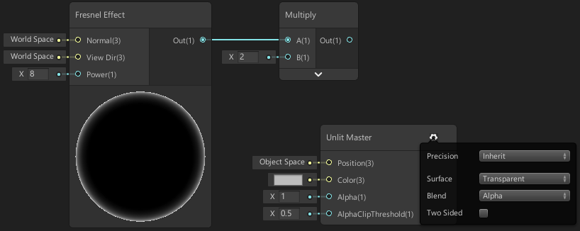
Before we start, we need to click on the small cog on our Master node and switch to Transparent rendering mode, with Alpha blending and keeping it to Single Sided. These will be important, as we will be using the Scene Color and Scene Depth nodes.
We’ll first create a Fresnel Effect node. This will output a value based on the mesh’s surface normal and view direction, producing what looks like a “glow” around the edge of the object. We can increase the Power input to make this glow closer to the edges – I’m using a value of 8. For more info about this node see the Fresnel Effect node docs page. I’m also putting this into a Multiply with a value of 2 to make it a bit brighter.
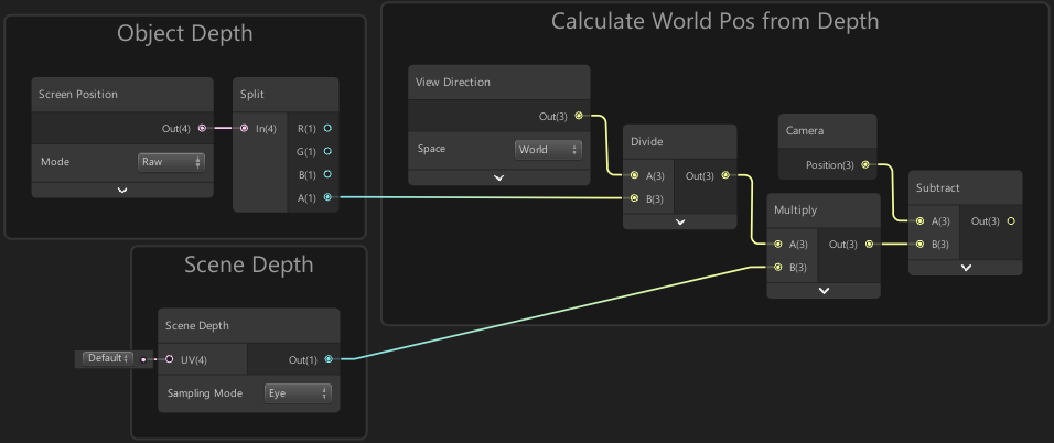
Next we’ll handle the intersection effect with scene objects. To do this, we’ll create a Screen Position node with the mode set to Raw and put it into a Split. This gives us the depth of the pixel/fragment on the surface of the object in the W/A component. We will also need to create a Scene Depth node set to the Eye sampling mode.
Because we want this shader to support distortion later, this will be different from the intersection effect made in the simple version of this shader – as we cannot use the Two Sided mode but still want the intersection to show for both front and back faces. The method I’m using for this is similar to what was done in the Water Shader Breakdown for the caustics effect. By knowing the position, object depth and the scene depth we can reconstruct the world position in the scene for that fragment, which we can then use to test if the fragment is on the edge of a hemisphere.
In Shader Graph v11 (Unity 2021.1+) the View Direction node is now normalised in all pipelines. We must use the newer View Vector node to achieve the correct result.
(Text in this post has been changed to account for this, but images have not!)
If you are using prior versions of URP, continue using the View Direction.
For HDRP, the graph at the end of the Fog Plane Shader Breakdown may provide a better example.
To reconstruct this world position based on depth, create a View Vector node set to World space, and Divide it by the object’s depth from the W/A component of the Split node from earlier. Then Multiply it by the output from the Scene Depth node. Create a Camera node, and take the Position output and Subtract the output from our Multiply. If you aren’t sure about how this works, see the water or fog-plane breakdowns linked above.
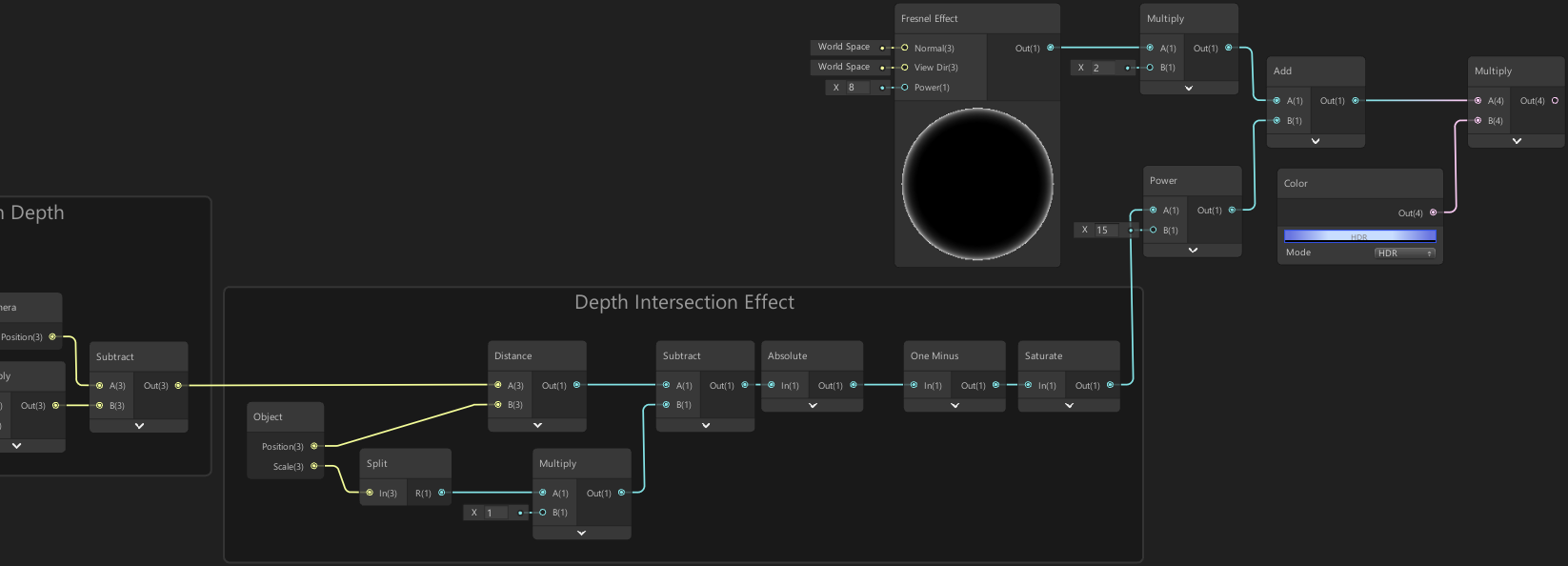
With this, we can do an intersection effect by comparing the distance from this position to the center of the forcefield (which will be at the object’s origin). Take the output of our worldspace scene position and put it into the A input on a Distance node. In order to get the object’s worldspace origin we’ll create an Object node and take the Position output and put that into the B input.
Currently this gives us values of 0 close to the forcefield origin, while the further parts has a higher output. Since we want to draw the intersection effect on the edge of the forcefield we need to take the output from the Distance and Subtract a value from it (I’ll come back to what value in a second), then take the Absolute. This will push those distance values of 0 into negatives then uses the absolute to “flip” them into the positive again.
The value in that Subtract should be based on the forcefield scale. We can obtain this by taking the Scale output from the Object node. This is a Vector3 however, and we only want a Vector1 so we’ll put it into a Split node and take the X/R component. You may also need to Multiply this by an additional scaling value if the scale of the mesh doesn’t have a radius of 1 (aka 2 units wide).
We’ll then take the output from the Absolute and put it into a One Minus node as we want values of 1 on the forcefield edge instead of 0, then put it into a Saturate node and a Power node with a second value of 15. Then Add the output of our fresnel’s Multiply to this. We will then Multiply by a Color node (or property if you want to be able to edit it from the inspector), to tint the forcefield to a blue colour. I’m also using HDR mode with an Intensity of 2.
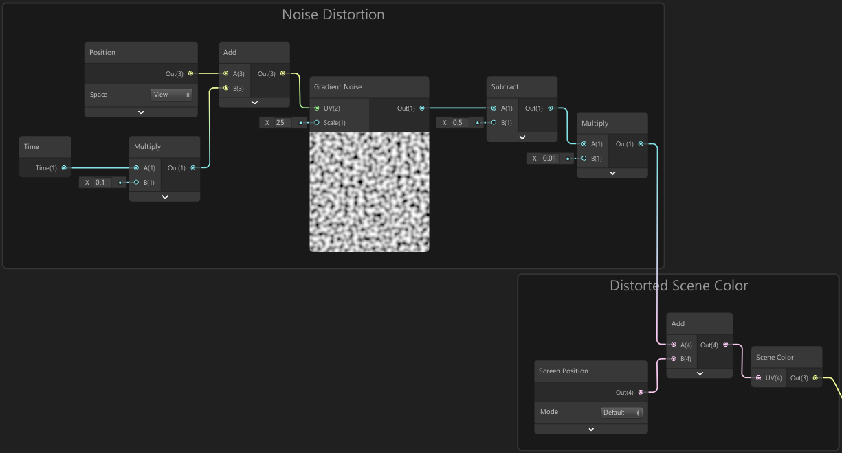
If you temporarily put this into the Color input on the Master node you should see that the forcefield is black, but you can see the blue edges where it intersects with objects in the scene. Unlike in the simple version of this we won’t be making the forcefield actually transparent as we want to add distortion. To do this we will use the Scene Color node, which is a texture of all the opaque objects the camera has rendered. Before sampling this texture, we can offset the coordinates slightly to create distortions.
Create a Screen Position node and put it into an Add node in order to handle this offset, leaving the other input empty for now. Then put the output of this into a Scene Color node. We’ll then take the output of that and put it into the A input on a Lerp node. Put the forcefield Color node we used earlier into the B input and put a Vector1 node with a value of 0.02 in the T input. This will allow us to interpolate between the scene colour and the forcefield colour based on a value which will control the visibility. Due to the forcefield colour being quite intense, we will want to keep this value very small. We can now take the Lerp output and Add it with our other colour (the output of the Multiply node from earlier) and put that into the Colour input on the Master node. We should now see the scene through the forcefield, but it isn’t distorted yet.
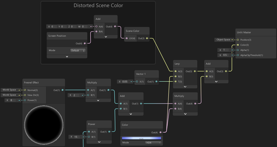
Going back to the Screen Position node from before, we need to offset it in order to create the distortion. We’ll use a Gradient Noise node to do this, with a Scale value of 25. As the output of this is between 0 and 1, we will want to Subtract 0.5 to move it into the range of -0.5 to 0.5 so we are distorting the view evenly in each direction. We can then Multiply it by a small value such as 0.01, to control the strength of the distortion, and put it into the second input on the Add node (the one with the Screen Position going into it).
We can also offset the UVs over time so that the distortion moves. Create a Time node and take the Time output and Multiply by a value of 0.1 to control the speed of the scrolling noise. Then put it into an Add node with a Position node set to View space. Put the output of this into the UV input on the Gradient Noise node.
Ripples
So far we have a nice forcefield effect, but one of the things I wanted to add was a rippling reaction with projectiles that are fired at the forcefield as seen in the GIF in the original tweet. In order to do this we need to use a Custom Function node, as we need access to a couple things that aren’t yet supported in shadergraph normally. This function will output a Vector3 distortion direction which we will use to further offset the Screen Position going into the Scene Color node. It will also output a Vector1 value which will allow us to colour the ripple slightly to make it more obvious. Note that I’m focusing on the front faces only here – it may be possible to extend it to the back faces too, however I won’t be going through that in this post.
In order to allow for multiple ripples to be handled at the same time, we will need an array to store the positions of the origin of each ripple. We will then also need another value to control the lifetime of the ripple. To send these points into the shader we will need a C# Script, which will also control updating the lifetime and removing the point when it reaches a lifetime larger than 1. Since we have 4 values, we could use a Vector4/float4 array for this – but as we might want to add more values to control further things (such as power/scale, perhaps even a different colour for each ripple) I will be using a float array.
It is possible to have arrays in shaders. Although shadergraph doesn’t support them normally we can still use a Custom Function node to declare the array and loop through it. We will need to be using the File mode in order to do this, as it needs to be specified outside of the function itself (which can’t be done using the String mode).
When defining the array we also need to specify a fixed length. We’ll be allowing our shader to store up to 6 ripple points, each having 4 components (3 of which are the XYZ position, and the final being the lifetime, as mentioned before), this means we need an array of length 6*4. We’ll come back to the actual shader function later.
|
|
If you want more information about arrays in shaders see this article by Alan Zucconi.
In order to initialise the array it has to be done externally, via a C# Script using Material.SetFloatArray(array).
The script I’m using looks like the following :
|
|
This script is just replacing the points in the array with random points when they reach the lifetime of 1 – so we get constant rippling effects for testing purposes. I won’t be going through the script for actual gameplay mechanics, but you would want to be able to:
- Add points based on collisions (e.g. MonoBehaviour.OnCollisionEnter/OnTriggerEnter). If there are no spaces for new points (if there are more than 6 collisions at once) but we want to add one, we would likely want to loop through the array and find the one with the largest lifetime and replace it with the new point.
- “Remove” points when they reach their lifetime of 1. Note : It’s important that the array length stays fixed and data is present when sending it to the shader so it can replace it correctly – so for removing points you will need to specify the values still, giving { 0, 0, 0, 2 } or something, where in the loop if the lifetime is 2 we know it’s a space for a new point, and our shader function should be outputting 0 to prevent anything being rendered for that point.
The following is the shader function used by the Custom Function node :
|
|
We specify the function inside the “void Test_float”, where the name of the function has to match the one given in the Custom Function node, in this case it was named “Test” – (But you can call it whatever you want)
We create some variables to hold the outputs, then loop through the array with the same length of 6*4 with “i += 4” so we can obtain all 4 values for each point in each iteration of the loop. We read the position and lifetime from the array via “_Points[i+n]” then set up the shape of the ripple based on the distance from the fragment’s position we passed in, and the point’s position.
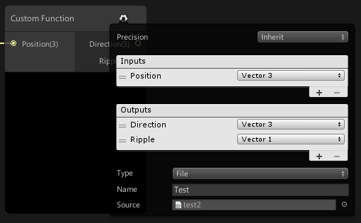
This function needs to be saved in a HLSL File (in this case I saved in under “test2.hlsl”, but call it whatever you want). Set the file as the source on the Custom Function node by clicking the cog icon on it. We also need to make sure we have a Vector3 input, and the Vector3 and Vector1 outputs defined on the node (I’ve named these Position, Direction and Ripple, they don’t have to match the same names as the function code – but they do have to be in the correct order).
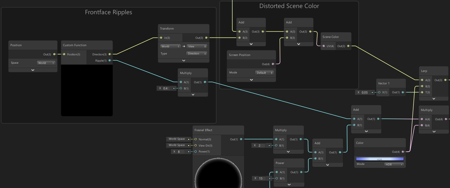
We next need to take the Direction output from our Custom Function node and put it into a Transform node from World to View space in Direction mode. We can then take the output of that and Add it to where we are offsetting the Screen Position into the Scene Color node.
Also, take the Ripple output from the Custom Function, Multiply it by 0.4 then Add it to the colour output right before the Multiply with the forcefield colour.
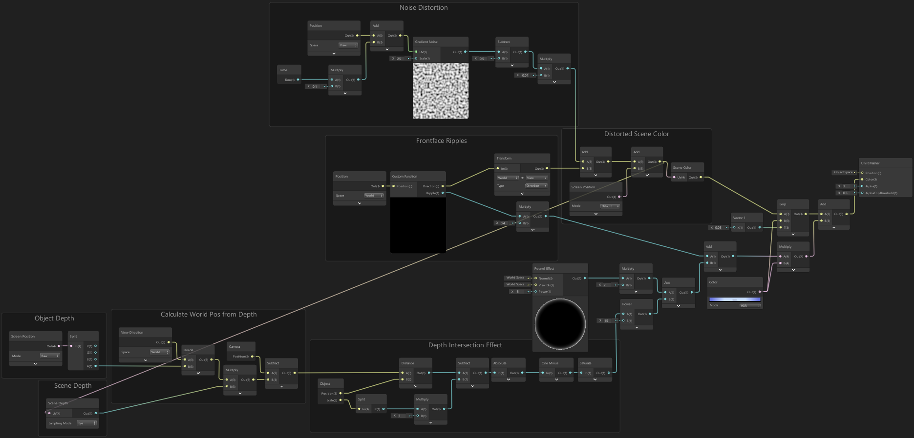
We should also take the distorted screen position output (from the Add node, before going into the Scene Color) and put it into the input of the Scene Depth node we made earlier. This will make sure we sample the distorted depth value so the intersection effect will be accurate to what is being viewed through the forcefield. I haven’t put these nodes close together so this will put a long line across our graph, hence why I’ve left this last to prevent confusion with other node connections.
Here’s a final image of the full graph, also showing that connection :
Thanks for reading! 😊
If you find this post helpful, please consider sharing it with others / on socials
Donations are also greatly appreciated! 🙏✨
(Keeps this site free from ads and allows me to focus more on tutorials)