Fractured Cube Breakdown
Intro
I recently made this fractured cube using a technique known as Pivot Baking, which I’ve wanted to try out for a while now. The cube is actually a pre-fractured model (made in Blender, using the Cell Fracture addon). But importantly, the positions of the origin/pivot of each fractured piece has been baked into mesh data (UV channels). In the shader we obtain these pivots, compare them to another position sent into the shader and use that to displace vertices (as well as scale & rotate).
At the end of the post I’ve also shown some other tweets I did using the same fracturing effect/technique, as well as listed links to effects other people have made.
Breakdown
Fractured Mesh
The first step is creating the fractured mesh. I used Blender, with the Cell Fracture addon which is perfect for this. But it first needs to be enabled under Edit → Preferences → Add-ons.
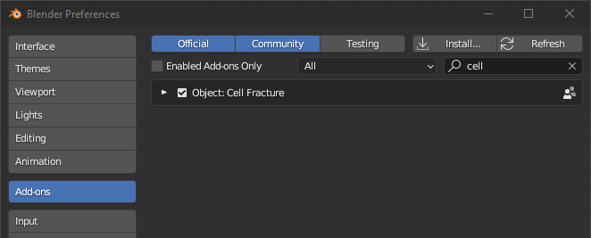
(In the search box, enter “cell” and the list should have “Object: Cell Fracture”. Tick the box just before the text to enable it)
I didn’t really intend this to be a Blender tutorial but I’ll still go through the steps I did! We’ll be moving to Unity & ShaderGraph later on~
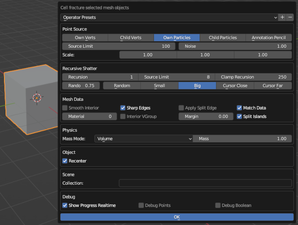
In Object mode, select the cube and use the Cell Fracture (either use the F3 search function, or you can find it under Object → Quick Effects). A box will appear with the settings for the effect. Under the Point Source heading, you’ll likely want to set the Noise to 1 so the fracturing isn’t uniform, you may also want to play around with the Recursive Shatter settings. Under the Mesh Data I’d recommend unticking the Apply Split Edge to avoid duplicating vertices along those faces.
Click OK to fracture the mesh. You can then hide (or delete) the original cube as it’s not needed. The mesh should be fractured into different objects but we’ll want to recombine them. Select a piece (to mark it as the active selection), then select all pieces (A, either one or twice depending on if you have Select All Toggles enabled in preferences) and use Object → Join (Ctrl+J).
You’ll then want to move the origin back to the cube center, which can be done by using one of the settings under Object → Set Origin. I’ve used Origin To 3D Cursor since my cube and the 3D cursor are both at the origin.
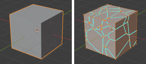
Resulting fractured cube, shown in Object and Edit modes
If the cracks made by this are very noticeable, you can try undoing & repeating the process with a larger mesh then scale down after. Or alternatively scale together the vertices manually (and snap them to edges) - though that could take a while depending on how many pieces there are.
Pivot Baking
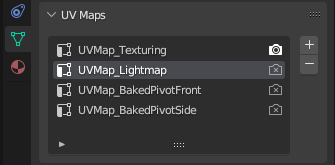
For baking the pivots, go into the Object Data Properties (green triangle icon in Properties window, usually on the right side of the screen). Under UV Maps add an extra 2 UV maps by pressing the + button. May also want to rename them.
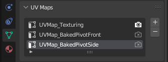
You can leave the first UV map if you want to be able to apply textures to the model (though the interior faces created from fracturing might need re-unwrapping).
Select the UV map for pivot baking (UVMap_BakedPivotFront) and follow these steps :
- Go into Edit Mode, Select all vertices/faces (A)
- Go into Front Orthographic view (numpad 1, can also press the green circle (-Y) on the gizmo in the top right)
- Unwrap using UV → Project From View (Bounds)
- Under the UV Editing workspace, change the Pivot (at top, just left from the magnet) to Individual Orgins
- Select all vertices on the UV map (A)
- Then scale to zero (S, 0). Should now have a bunch of points (one for each fractured piece)
Repeat this for the other UV map (UVMap_BakedPivotSide), but with Right Orthographic view (numpad 3) instead.
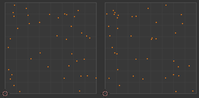
The resulting pivot UV maps will look something like this :
Export the model as an FBX file and import into Unity. You’ll likely want to make sure you export with the correct axis/scale conversions. (I typically use -Z Forward, Y Up, with Apply Transform enabled)
Pass Position into Material
Moving into Unity!~ Drag the fractured cube into the scene. You’ll want to create a Lit Shader Graph, and a Material using it that we can assign to the cube object.
Before we start with the shader itself, it’ll be useful to first set up a new GameObject, which I’ll refer to as the “Handle” object. This will be what controls the fracturing effect when we move it around in scene/game. On this object, we’ll add a C# script that will send the transform.position and transform.localScale.x into the shader/material. For example :
|
|
With this, you’ll be able to properly test the shader in the scene view later on (i.e. each time after editing the vertex stage, so you can visualise how the changes actually affect the result - as the node previews themselves won’t be useful for that)
Since we use transform.parent, this Handle GameObject should be set as a child to the Fractured Cube GameObject. But alternatively, you could add another serialised field for the Material asset itself, or for the Transform or MeshRenderer of the cube to be able to obtain the material that way, as explained in code comments above too.
We’ll also need to set up the properties being used by the script above in the Blackboard inside the graph :
- Vector3, named “Pos”
- Float, named “Radius”, and set it’s Default value to 1 (under Node Settings tab of Graph Inspector)
Obtain Baked Pivots in Shader Graph
In order to get our baked pivots, we’ll need to access the UV data by using two UV nodes. In the twitter gif the pivots were actually baked into UV0 and UV1 as I only used a total of 2 UV channels in Blender (because I didn’t need to apply any textures).
But if you have that original UV map, like in the Fractured Mesh section of this post, you can use the UV1 and UV2 channels instead. Either way, I’ll be referring to these as the “first/second Pivot UV set”.
Additional notes about UV channels
Unity also uses the UV1 channel when objects are baked into lightmaps, so if you want to support Baked Global Illumination, you’ll need to provide an additional UV channel for this. Or get Unity to generate them (see Unity docs : Generating lightmap UVs), but you’ll still need to export with it in the list (or it’ll override the pivot data).
In this case the pivot UV maps would be passed into the UV2 and UV3.
You also wouldn’t be able to have any more UV maps here, as Shader Graph currently only exposes 4 channels (UV0-UV3), despite the Mesh class supporting up to 8.
Though it’s also worth noting, technically these channels can be up to Vector4 in Unity - but Blender/FBX files only deals with 2 axis in it’s UV channels. So we’ll only be using the X and Y axis (also labelled R and G). But if you wanted, you might be able to write a C# script (perhaps an AssetPostprocessor?) to combine them into a single UV channel. Not sure.
Put each of these UV into a Split node and create a Vector3 node. Put the R output from the first Pivot UV set into X, and R output from the second UV set into Z. The Y input can be set to the G output on either Pivot UV as they should both be equivalent (since the vertical axis is the same for the front and side axis).
As we used Project From View (Bounds), we’ll need to Remap the values a bit. The bounds of the UV is 0-1, so that’ll be the In Min Max. The default blender cube is 2 units wide, so I’ve set the Out Min Max to -1 and 1. I then needed to Multiply by (-1, 1, -1) likely due to some axis differences. (Perhaps if we projected from different views we wouldn’t have to do this).
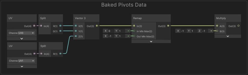
This gives us our baked pivots (in Object space), It’ll be a good idea to group these nodes (named something like “Baked Pivot”) as we’ll need the output of this multiple times!
Shader Graph - Vertex Stage
What we’re trying to achieve is : As we move our Handle GameObject position (“Pos”) closer to these baked pivots, the strength of the displacement will be larger (and intensity of the emission colour should increase too).
The position being passed into the shader is in world space though, so before we can compare them we’ll need to use a Transform node from Object to World space on our pivots (or World to Object on the “Pos” property, if you prefer).
Alternatively we could adjust the C# script to pass the position in object space (may be more performant), but that would require the Handle GameObject to be a child of the cube (to use transform.localPosition), or we would need a reference to the cube object/transform to use float3 localPos = cubeTransform.InverseTransformPoint(transform.position);. I didn’t do this in my original shader, so will leave it up to you.
We can then use a Distance node with our “Pos” property. Put this into the A port on a Divide node with the B set to the “Radius” property to take that into account. Now if our Handle GameObject is close to each pivot, this returns a value close to 0, while as we move the object away the value will increase.
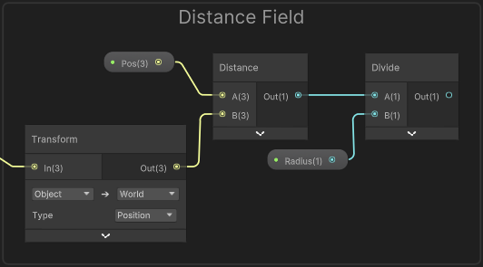
A value of 1 would mean the object is “Radius” units away, which should be roughly where the effect returns to a regular cube (no displacement or emission colour). To obtain that we could use a One Minus then Saturate - that would be a value of 0 at the radius, and 1 where the Handle GameObject and pivot positions match… but to have better control, we can instead put it into a Smoothstep node.
Or could alternatively use Inverse Lerp for a more linear falloff. Either of these give us control over both the min and max edges. You’ll want to put this into a group named “Strength”.
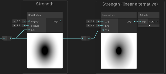
Two options for how to set up strength values. Later you could try both and see how it affects the graph.
From the previews you can see this too, but this means that when the distance is smaller (or equal) to Edge1/A, the result will be 0 (black), while larger (or equal) to Edge2/B, it’ll output 1. And in between these values, a gradient from 0 to 1 is produced.
In the case of the Inverse Lerp it isn’t clamped by default so produces values that are negative and larger than 1, hence why we also need a Saturate to clamp them between 0 and 1.
I’ve set the inputs to 0.2 and 1.2 as shown in the image above, but you could adjust them slightly for different results. To have control from the Material Inspector you may also want to set up a Vector2 property (with default value of (0, 1), and named “StrengthMinMax” for example), drag it into the graph, Split and connect the R and G outputs to these edge inputs instead.
Moving onto the vertex displacement, we’ll need to use a Position node set to Object space to obtain the mesh vertex positions. There’s a number of ways we could adjust these positions but the tweet includes :
- Scaled down from baked pivot
- Rotated around baked pviot
- Scaled down from cube/object pivot, which will be
(0,0,0)in object space
All three of these are based on a strength value (like what we just calculated above). Specifically, I used the same strength for the first two, but for the last one I used a second Smoothstep with different Edge input values so there is more variation. We’ll go over that later when we need it.
In the twitter gif using these two strength values allowed the fractured pieces to start shrinking/rotating before they moved outwards from the cube center. But with different values it could also do the opposite, hence why it may make sense to use exposed properties to set these.
Gif showing alternative fracture. Graph is the same, but different Min/Max on strengths. “Strength” min is quite high (0.8, 1), so pieces disappear (shrink to a scale of 0). Pieces also move outwards slightly before shrinking/rotating as Strength 2 (setup in a later section) is (1.5, 0).
Scale around Baked Pivot
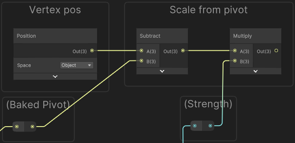
Anyway, to handle scaling around the baked pivot we first need to offset our vertex positions (Position) using a Subtract node, with the B input set to our Baked Pivots (output of group from earlier).
One way to help visualise this, is imagining a single pivot at some point in 3D space (or even 2D/1D), by subtracting it, it shifts the space so that the pivot is now at the origin (0,0,0). And our vertex positions for that fractured piece will be all around that (since the pivot is at the center of the piece).
We can now apply scaling using a Multiply node and the output from our “Strength” group.
Additional notes about scaling
While many with background in maths might already know this, I thought I’d still clarify exactly what happens when scaling/multiplying with different strength values :
- When strength is equal to 1 : the positions remain unaffected (anything multiplied by 1 is itself).
- When strength is larger than 1 : the positions would move outwards (from the origin of the space,
(0,0,0)). This won’t happen here as the Smoothstep only outputs values between 0 and 1, but we’ll be doing a different scaling later which involves this. - When strength is smaller than 1, the positions move inwards towards the pivot, so the fractured piece shrinks in size.
- When strength is equal to 0 : all the positions would be equal to the origin (since anything multiplied by zero, is zero).
If you were to output this currently, all our fractured pieces would be on top of eachother, centered at the cube’s origin. We’ll need to shift the vertex positions back around the pivots, but before we do that, we should handle the rotation (otherwise we’d be rotating around the cube origin instead).
Rotate around Baked Pivot
To handle the rotation we can use the Rotate About Axis node. We could make each fractured piece rotate around a different axis (e.g. by using the Baked Pivot as a seed to generate a random value), but I found this made the pieces intersect with eachother too often which looked messy. Instead, I just set the axis to (1,1,1) - which’ll be normalised automatically by the node.
For the rotation we can use the strength value from earlier, but it also needs to be inverted. Before when scaling we needed a value of 1 when the distance to the pivot is larger than the radius to make the scale remain unaffected. Here however, we need a rotation of 0 so the input stays the same. For this we can use a One Minus node.
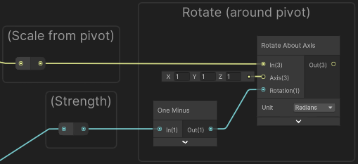
The rotation mode here is in Radians, but you could also work in Degrees mode if you prefer. Since the range of our strength is currently just 0-1, that would mean 1 degrees of rotation which is not very much so you would need to additionally Multiply by some value (e.g. 90) to set the maximum amount of rotation.
While the above works, I didn’t want all the pieces to rotate in the same direction so for some I flip/negate the strength. To handle this we need to generate a random value for each fractured piece. It’s easiest to do this using the Random Range node but that takes a Vector2 seed rather than a Vector3. I chose to Swizzle the Baked Pivot, taking only the X and Z axis (“xz” in text field). This means pivots aligned on the Y axis will rotate the same direction, but that’s not that common to be noticeable.
(For older versions of Shader Graph, the Swizzle node may look different - could use Split and put R and B outputs into a Vector2 node as an alternative)
For the Min and Max on the Random Range, I’ve set it to -1 and 1. It generates values inbetween these but as I only want to know if it’s negative or not, I used a Sign node (not to be confused with Sine!). We can then Multiply this with our inverted strength (from the One Minus). Put this into the Rotation port on the Rotate About Axis using Radians mode.
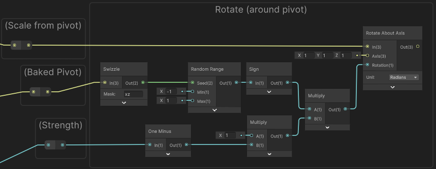
(Use value in Multiply to set the maximum amount of rotation. e.g. 3.14 would mean it rotates Pi radians / 90 degrees)
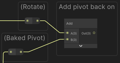
Now that we’ve handled the scaling and rotation around the baked pivots, we need to Add the Baked Pivot position back on (same thing as we subtracted before). This shifts the origin (0,0,0) back to the pivot (along with the vertex positions around it - but easiest to think about the space origin specifically), so our fractured pieces are moved back to where they belong!
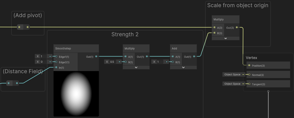
Scale around Cube/Object Pivot
I wanted the fragmented pieces to also move outwards from the center of the cube. As we’ve shifted our vertex positions back to the pivots, the space origin (0,0,0) is now the cube center again, so we just need to apply another scaling via a Multiply node. As mentioned earlier I use a separate strength value for this :
Take the output of the Divide node again (output of “Distance Field” group) and put it into a second Smoothstep node, with an Edge1 of 1 and Edge2 of 0. (The first edge here is higher so that we don’t need to invert the result)
We Multiply by a value (such as 0.5) to set how far we’ll be scaling, then need to Add 1 since we want to scale the pieces outwards rather than into the cube (which means the range of values needs to be above 1). Put the result of this into the Multiply with our vertex positions.
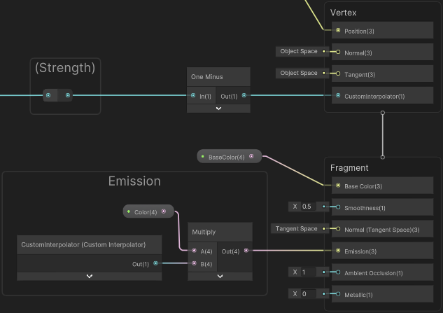
Shader Graph - Fragment Stage
The fragment stage isn’t really that interesting here as it’s just a Color node (or property) connected to the Base Color and another for Emission ports on the Master Stack. But as that emission is based on a strength value from earlier I thought I’d mention how to connect this up.
While you may think to just take the output of the “Strength” group, One Minus, and try to connect it… Shader Graph won’t always let you connect nodes between the two stages.
Technically, assuming there aren’t Fragment-Only nodes in the chain, it is possible to connect an output from the vertex stage to the fragment if you temporarily unconnect the chain from the Vertex stage, or use an additional node like Preview. But this isn’t really recommended and would also be equivalent to just copying the nodes / recalculating the value.
You could do that, but in this case it would be better to use a Float Custom Interpolator to pass the value from the vertex stage through to the fragment stage. This way, we’re only doing the calculation once, but it does require Unity 2021.2+ to use them. I’m not going to go over them here, so if unsure how to set one up see : Intro to Shader Graph - Custom Interpolator.
In the fragment stage, we can then use the associated Custom Interpolator node to obtain the value, tint (Multiply with a Color node/property) and connect to the Emission port.
Additional Examples
Thanks for reading! Below I’ve listed some additional examples (my own and some external links to pivot-baked effects others have made)
Fractured Forcefield
The fracturing part of the shader here is the same as this post, but the effect uses a dome mesh rather than a cube. For more info, click foldout below.
More Info
The dome mesh includes a base circular face, as the Cell Fracture plugin in Blender doesn’t work great if the mesh has holes. The fractured faces for this part can be removed after. Also if you tick “Interior VGroup” in the Cell Fracture settings (under Mesh Data heading), you can easily delete all the interior vertices later in Edit Mode, by selecting them via the Vertex Groups list (under the Object Data Properties / green triangle).
The forcefield is similar to the one from my Forcefield Shader Breakdown, but I didn’t include a Fresnel Effect or the ripples. Partly as the dome mesh I used didn’t have the correct normals at the time, but I also preferred the simpler look. If the mesh doesn’t have perfect normals, may need to use a Data Transfer modifier to transfer smooth normals from an unfractured dome to fractured dome but that’s not something I tried. We could also calculate normals in the shader by normalising the vertex positions (Position node) since the vertices lie on a sphere.
This also ignores recalculating the normals duing the vertex displacement. If that’s something you want, should be able to use another Rotate About Axis with the same inputs but on the normal.
If you render the effect with Transparent surface mode and partial alpha, the fractured faces might be visible as faces overlap. (Especially if Render Face is set to Both or if the dome mesh itself contains some thickness). To prevent this you can do a Transparent Depth Prepass (see that heading under FAQ : Issues with sorting Transparent faces/objects).
If using the Scene Color node and keeping Alpha set to 1 (like in the forcefield breakdown linked above) that will also prevent you seeing the fractured faces, though they will still be rendered. If many faces are overlapping you could still use a the prepass to reduce the overdraw cost.
Fractured Plane
The effect here is similar, but uses a plane mesh, a Render Texture as an input for strength values (rather than the Distance to the _Pos) and applies some vertical displacement rather than scaling from origin. For more info, click foldout below.
More Info
When creating the fractured plane mesh in Blender, we can use a Scale of (1, 1, 0) in the Cell Fracture Settings (under Point Source heading). This makes the fractured edges perfectly vertical along the up axis (which is Z in blender). When creating the Pivot Baked UV map, we only need one additional map using Project From View (Bounds) on the Top Orthographic view (numpad 7).
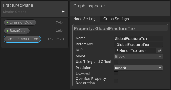
In the fractured shader (described in this post), we need an Texture2D property named “GlobalFractureTex” (with reference as _GlobalFractureTex). Untick Exposed in the property settings.
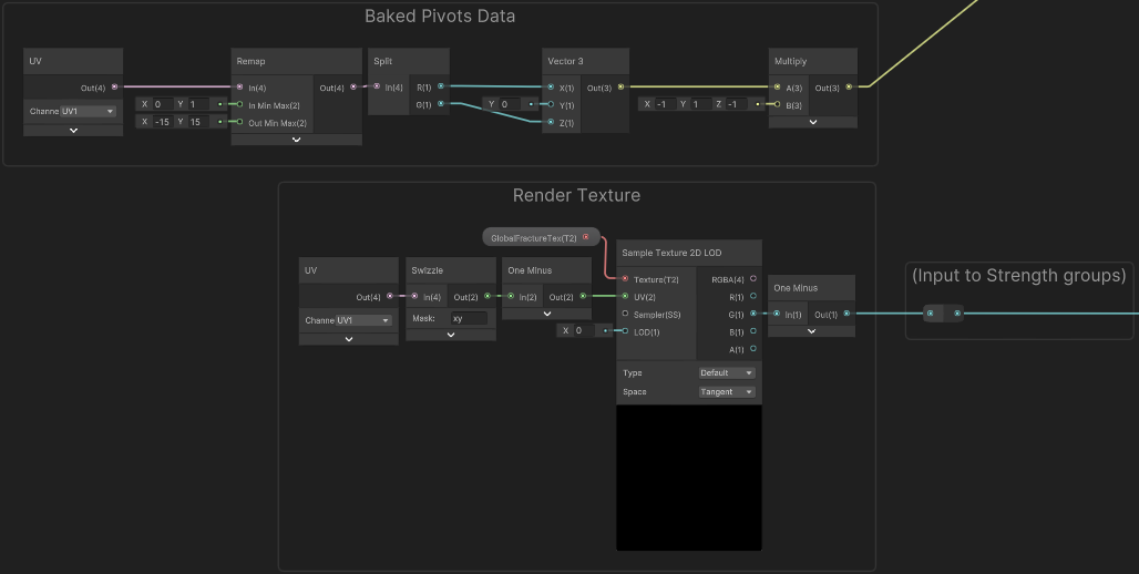
As shown below, we sample the texture with a Sample Texture 2D LOD node as it needs to be connected to the vertex stage. The G output of that is used in the “Strength” group (Smoothstep node). The “Baked Pivots Data” group is also slightly different since we only have one Pivot UV map (passed into UV1 in this case, as UV0 is used for regular texturing). My plane mesh has a scale of 30 units, so (-15, 15) is used in the Remap.
“Strength 2” and the “Scale from Object Origin” groups have been removed, as scaling the fractured pieces from the center of the plane looks a bit odd.
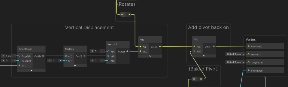
A new group which applies some “Vertical Displacement” has been added, in-between the “Rotate” and “Add pivot back on” groups, which is connected straight to the Position port on the Master Stack.
For creating & painting into the Render Texture, the following C# Script is used. It handles raycasting to the plane from mouse position. The resulting point is remapped and passed into a “brush” shader (shown below the script) that is used with a Graphics.Blit call to draw/paint into the texture. It’s only a proof of concept, so has a few hard-coded values (like plane position and size) and could probably be optimised (e.g. using Shader.PropertyToID). I’ve also removed some of the beam VFX related parts as that isn’t the focus of this post.
|
|
For the blitMaterial used in the script above a Material is using the following Unlit Shader Graph.
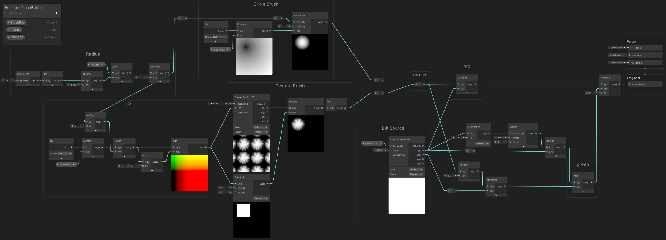
(Click image to view fullscreen)
Can optionally use the “Circle Brush” or apply a “Texture Brush”. Ideally you’d want that to Clamp, but to avoid artifacts around the edge I chose to mask it using a Rectangle node.
“ScaledTime” here is a Subgraph which uses the Time output from the Time node and multiplies by the Speed input. The Sine adds a bit of variation to the brush size, but this is optional.
As commented in the script, the purpose of the shader is :
RED channel : draws "brush" (circle or texture) at the "_BrushPos" passed in- This is used in a separate shader (not shown here) which has a downward displacement and draws channel as black to look like the ground is scorched after the top layer has broken away.GREEN channel : for red pixels > some threshold, add some small value- Used in the fractured shader to keep destruction animated
External Links
Some more examples using this technique (mostly fracturing floors or portal effects) :
- Twitter - Thomaz Nardelli (@zazamorga)
- Twitter - Klemen (@klemen_lozar)
- Gears Hammer of Dawn Case Study (Lexdev)
- Twitter - Mark Mayers (@DesolusDev)
- Twitter - Harry 💬 (@HarryAlisavakis)
- Twitter - Matt Ostertag (@matt_ostertag)
- Youtube - UV Pivot Baking in Houdini/UE4 (Okari)
- Twitter - Lukas Schneider 🌳 (@zwitscherluki)
Thanks for reading! 😊
If you find this post helpful, please consider sharing it with others / on socials
Donations are also greatly appreciated! 🙏✨
(Keeps this site free from ads and allows me to focus more on tutorials)