Waterfall Shader Breakdown
Intro
Back in 2019 I shared this waterfall shader that interacts with a sphere - pretty sure it’s my most popular tweet. For a while there’s been comments in the thread explaining some parts of it, but I’ve also wanted to write a proper breakdown of the shader. It’s quite stylised (which probably comes as no surprise given the usual stuff I do), but the technique could apply to other art styles too.
The basis of the interaction effect uses a SDF (Signed Distance Field) of a sphere, but the Y position is clamped so that a hole is created below it. To make it appear more fluid-like, this hole and the waterfall sides are distorted with a sine wave and alpha clipped. Scrolling noise is used to add foam to make it look more like flowing water.
Apparently I don’t have the shadergraph file anymore so had to recreate it, but I’m pretty sure the old graph was much messier and over-complicating a few things so that’s probably a good thing!~ 😅
Breakdown
Mesh
This isn’t a Blender tutorial but a quick note about the mesh the shader is applied to : It’s mostly just a rotated quad/plane with the top edge extruded backwards and a bevel added. It doesn’t need to be that tessellated/subdivided as there’s no vertex displacement in the shader.
The horizontal part of the waterfall is 2 units wide, which isn’t that important but the value of 2 will be used in the shader a couple times. If you have a different scale, you can use that value instead.
The mesh does also need to be UV mapped. For that, I selected the face at the base of the waterfall (to set it as the active face), then toggled all faces selected (with A key) and used UV heading (or U key) -> “Follow Active Quads”. It doesn’t matter that the UVs go outside the 0-1 range.
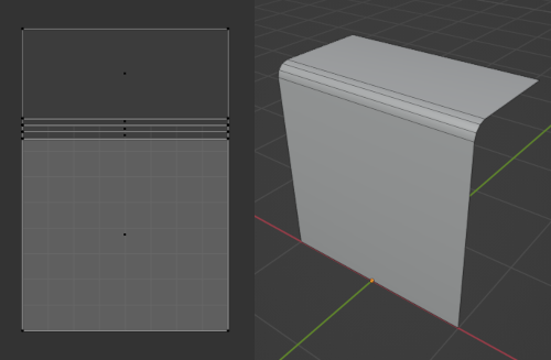
Image showing mesh in Blender. On the left, the UV mapping.
Pass Position into Material
In Unity, You’ll want to create a graph (I’ve used an Unlit Shader Graph), and a Material using it that we can assign to our waterfall.
You’ll also want to create a Sphere as a child of the waterfall GameObject - this’ll be used for interactions. The following script is attached to it which passes the position and radius to our material :
|
|
We’ll also need to set up the properties being used by the script above in the Blackboard inside the graph :
- Vector3, named “SpherePosition”
- Float, named “SphereRadius”, may want to set it’s Default value to something larger than 0
- (or a single Vector4 property if combined like a comment in the code mentions)
Under the Node Settings tab of Graph Inspector while the properties are selected, make sure their Reference fields match the strings set in the script. In versions 2021.2+ it’ll automatically use the name with “_” appended but note that previous versions default to a autogenerated string and will need to be changed.
Shader Graph - Interaction
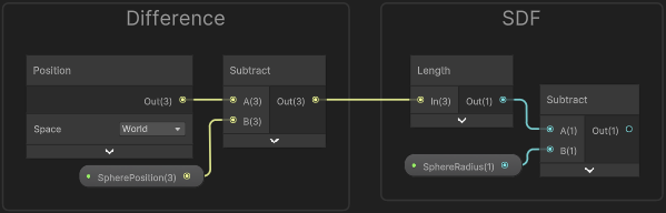
To handle the interaction, we need to calculate the distance to the sphere for each fragment. This could be done with a Distance node… but we’ll instead Subtract the SpherePosition property from the Position node (set to World space), then put this into a Length node. It’s the same calculation but will make the steps later slightly simpler.
That gives us the distance to the SpherePosition passed in, but that’s just the center of the sphere. We need the distance to the edge (or face I guess) of the sphere. Luckily, spheres are super simple shapes and the distance to that is given by the radius, so if we Subtract the SphereRadius property it results in values of 0 for fragments that intersect the sphere. Fragments outside the sphere are some positive distance away, and inside the sphere will be negative. This calculation is known as the Signed Distance Field (commonly shortened to SDF) of a sphere.
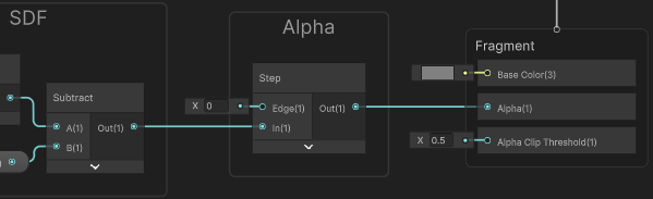
Right now it’s a bunch of distances per fragment - we’ll want to do some comparisons to check for values that lie inside the sphere. We could use Comparison (GreaterOrEqual) and Branch nodes but since we want a 0 or 1 output it’s equivalent to using a Step
We can put the result of this SDF into a Step node with an Edge value of 0 (since we’ve already subtracted the sphere radius). Make sure the ports are the correct way around or the result will be inverted.
It’ll be a good idea to right-click this node and put it in a group named “Alpha”. We’ll now need to enable Alpha Clipping under the Graph Settings, then connect this to the Alpha port on the Master Stack, leaving the Alpha Clip Threshold at 0.5.
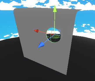
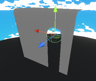
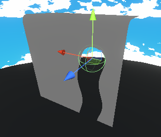
By saving the graph and visualising in the Scene View, you should see that if you hide/disable the sphere’s MeshRenderer temporarily, a hole is left in the waterfall which moves and scales with the sphere.
That’s neat, but we’d like the hole to continue below the sphere to look like it’s parting flowing water. Since we subtracted the SpherePosition from our fragment Position, “below” in this case is any Y coordinates smaller than 0. If we clamp the negative values to 0, that would keep them inside the sphere and therefore be clipped.
We only want this clamping on one axis, so will need to use a Split node. There’s a few ways to handle it, for example putting the G output through a Maximum node with a value of 0, then into the Y port on a Vector3, also connecting R to X and B to Z. The image below also shows another alternative - can use whichever.
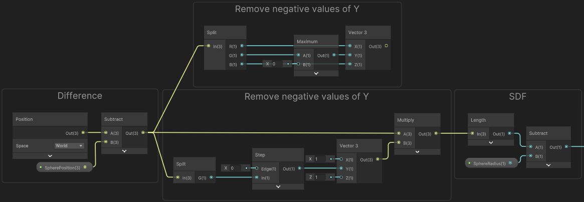
Visualising in the scene we now see the hole being stretched downwards.
Before moving on, let’s take the output of the SDF again and put it into another Step node. This time setting the Edge input to some small value, like 0.05. I’ve converted this to a Float property named FoamEdgeThickness.
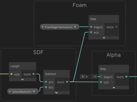
As shown, put this in a group named “Foam”. You can temporarily connect this to the Base Color port in the Master Stack if you’d like to visualise what it’s doing. It’s the same as the alpha, but offset slightly, so gives us a black outline around the hole. Later this will be recoloured.
Shader Graph - Sine
Currently this hole created by our sphere-interaction is static, so the result doesn’t look that water/fluid-like. We need to add some movement but I’ve avoided Vertex Displacement here as that requires the mesh to have quite a few vertices, otherwise it won’t look smooth. Instead we’ll offset the positions used in the SDF calculations.
The sides of the waterfall mesh are also static, so we should offset and clip some pixels there as well.
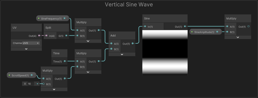
To add this movement I’ve used a Sine wave/node on the UV. The water should be wobbling side-to-side, which means the wave needs to be orientated along the vertical axis (G output from Split). We can Multiply by some value before the Sine to control the frequency and Multiply after to control it’s amplitude.
To make it scroll/move, use the Time output from the Time node, Multiply by some value to control it’s speed and Add before the Sine. You can use properties for the value inputs so it can be controlled from the Material, as shown below.
We now need to combine this Float output with our SDF position.
(click for some ramblings / older methods I used for this)
Since the positions used in the SDF calculations are in world space we can’t just put our float into an axis of the Vector3 node and Add/Subtract it, as that would remain orientated to the world axis even if the waterfall was rotated - try it and you’ll see the problem.
In my original graph from 2019 I feel like I made quite a mess of this. After a bit of trial and error I ended up using the inverse-model matrix (UNITY_MATRIX_I_M) but in a matrix multiplication as the second parameter (same as the matrix being transposed). In graph form, it would look like this :
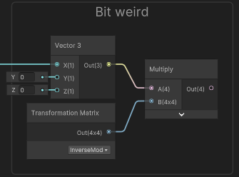
It does work. Normal vectors can actually be transformed this way too when there isn’t uniform scaling (e.g. see SpaceTransforms.hlsl), so it apparently kinda makes some sense. But when recreating the graph for this post I wanted to find a better way to handle it.
The Vector3 (with the float in the X coordinate) is basically in object space. We could use a Transform node to convert from Object to World space but with Direction mode that normalises the vector - which isn’t what we want (really wish there was a Vector mode as well).
We can use the Position mode instead, but as this also applies the translation of the waterfall GameObject, so we’d also have to Subtract the Position output from the Object node to remove that.
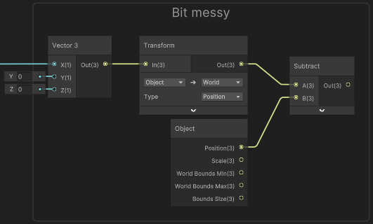
Again, works. Though I still find this a bit messy.
We could instead use the Transformation Matrix node with the Model matrix in the A port of a Multiply and promote our Vector3 to a Vector4 node, with a W component of 0 - as that’s how you handle matrix multiplication with vectors.
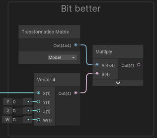
Maybe a bit more intuivite than what I had originally. But I realised there’s an easier way to handle it…
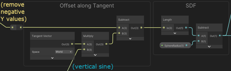
There is a Tangent Vector stored at each vertex. Along with the mesh normals it’s main purpose is converting tangent-space normal maps back into World space. The normals aren’t important here but to make the Tangent→World space transformation work, these tangents are aligned to the horizontal axis of the UVs.
That’s where we want our wobbly offset so we can just offset along these vectors. We need to select World on the dropdown so it’s in the correct space, Multiply it with our Sine group output and Subtract it from the Vector3 value just before the Length node.
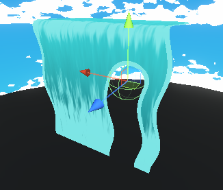
In the scene, it should now look something like this.
(SineFrequency=12, SineAmplitude=0.05, ScrollSpeed=1)
For the sides of the waterfall, we’ll add a UV node, Split and take the X/R axis and then Subtract a value of 0.5. From the preview you’ll see that this shifts the horizontal UV so it ranges from -0.5 to 0.5, with 0 being in the center (where the black begins). This is useful, as we can Absolute to make all values positive, allowing us to handle both sides of the waterfall at the same time. But before that, we want that wobble so need to Subtract the output of the Sine group divided by 2 (as the horizontal UV axis is a 0-1 range but our waterfall is 2 units wide).
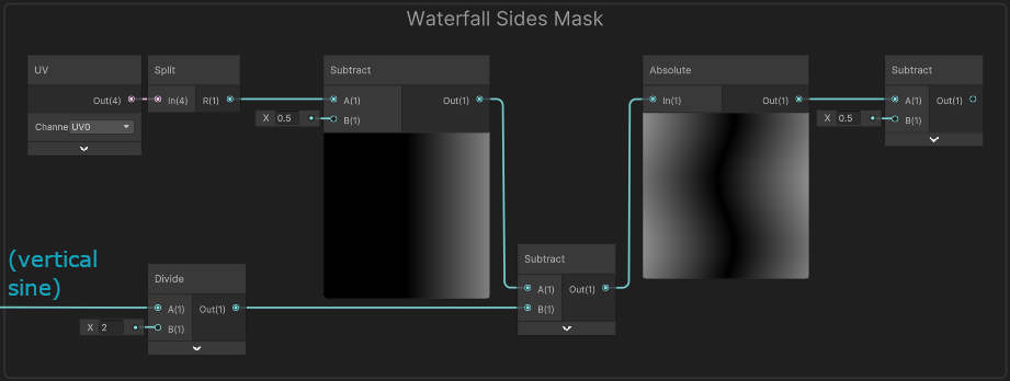
After the Absolute, both edges of the waterfall have a value of 0.5. We could use a Step node to compare this directly but we’re going to need multiple - so it’ll be more convienient if we Subtract 0.5 first as shown above.
It’ll also be cut off at parts due to our wobble, so we also need to offset by half of the SineAmplitude. Then put it into the Edge inputs on two Step nodes.
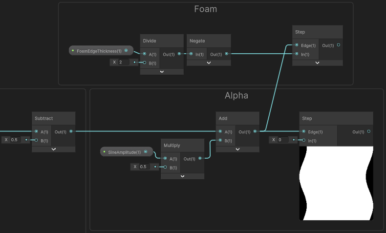
As shown, one of these Step nodes will be used for the alpha clip and needs a value of 0 in the In port. Put this in a group named “Alpha”, similar to earlier. The output of both of these Alpha groups needs to be multiplied together for the Alpha port in the Master Stack.
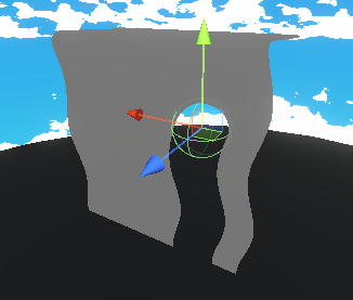
If you were to then visualise this in the scene, the edges would be wobbling too now :
The other Step should have some small negative value like -0.025, but if you created the FoamEdgeThickness property earlier, you may want to Divide that by 2 (again since the waterfall is 2 units wide), then Negate it for that port (as shown above). This’ll go in a group named “Foam”. These groups will also need multiplying together but we’ll worry about that later.
Shader Graph - Noise Foam
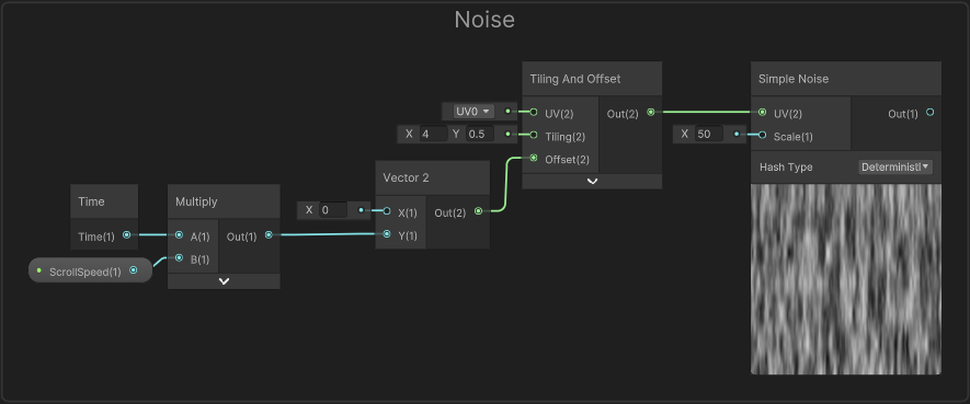
To make the shader look more like flowing water, we can apply some scrolling noise (via a texture or Simple Noise node).
To make it scroll we’d use the Time output from the Time node, and Multiply by a value to control the speed. We want it to scroll vertically, so put it into the Y port on a Vector2 node, which goes into an Offset port on a Tiling And Offset node. This can go into the UV port on our Simple Noise (or Sample Texture 2D if you use a seamlessly repeating noise texture instead)
We can use this noise to adjust the colour slightly (as shown in the next section) but I’d also like this noise to represent some foaminess to the water as it starts to fall at the top as well near the base. To handle that we’ll need some masks of those areas.
Based on the UV coordinates stored in the mesh, the base of the waterfall is where the vertical axis (G from Split) is close to 0. We could just use a One Minus node, but I’m using a Smoothstep instead as it gives a nicer result and better control over remapping the values.
If you want a more linear result, an Inverse Lerp could be used instead - that would also need a Saturate node to be clamped between 0 and 1.
The mask for the top / bevelled area of the waterfall is a bit more complicated but is similar to how we handled the waterfall sides (involving a Subtract, Absolute and another Subtract but with ports reversed to negate the value at the same time). The value in the second subtract represents the width of the area being mask, we then Multiply by a value to control the falloff, and Saturate to remove any values outside the 0-1 range.
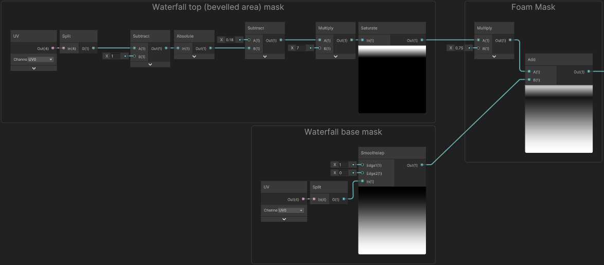
(Click image to view fullscreen)
The next step is combining these masks, which we can do with an Add or Maximum node. I’m multiplying the top mask by 0.75 first so it’s strength is a it lower.
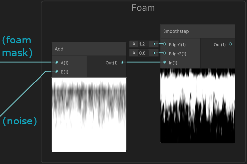
We could Multiply this with the noise, but I’m instead going to Add them together, then use a Smoothstep node with Edge1 set to 1.2 and Edge2 set to 0.9. But feel free to try out other values! Put these nodes in another “Foam” group.
Shader Graph - Apply Colour
We’re almost done, we just need to actually combine the groups we’ve made and apply some colours. Some nodes are grouped under headings of “Alpha” and “Foam”. Both sets of these need multiplying together separately. The alpha one should already be handled if you followed along, but we still need to Multiply together the Foam groups.
The result of this will be put into the T input on a Lerp node so we can interpolate between two colours. The A port needs to be set to a Foam Color property, while B will be used for the water colour.
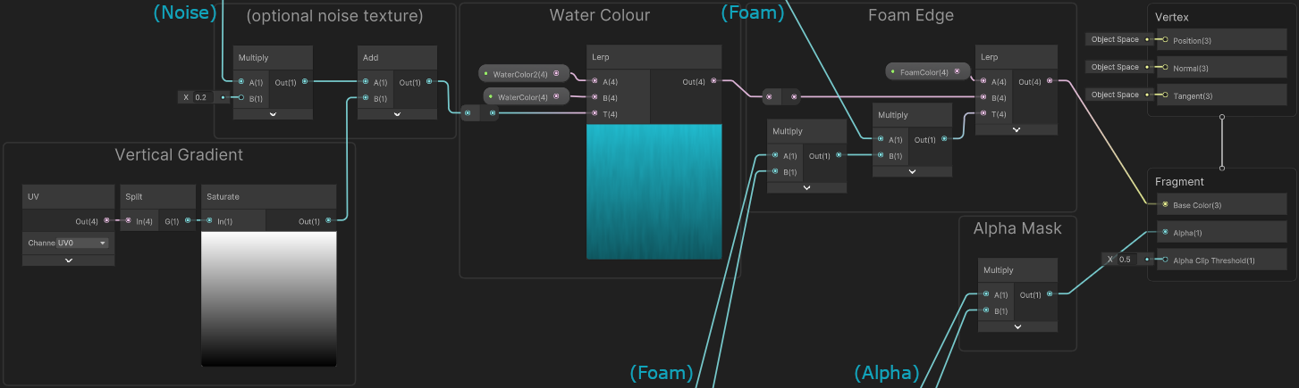
(Click image to view fullscreen)
We could have a single colour for the water, but as shown above I’ve used a vertical gradient and the noise from earlier (multiplied by 0.2) to add a bit of texture (wasn’t really in the original graph but improves the look a little). Those goes into the T input of another Lerp with A and B set to two Water Color properties.
It looks better in motion like the tweet and the start, but here’s the final result! Feel free to tweak the properties to adjust how it looks.
Thanks for reading! 😊
If you find this post helpful, please consider sharing it with others / on socials
Donations are also greatly appreciated! 🙏✨
(Keeps this site free from ads and allows me to focus more on tutorials)