Tentacle Shader Breakdown
Intro
Hey! I recently made this tentacle shader that wraps around a target object, as part of the current “Technically A Challenge”; a challenge run by the “Technically Speaking” discord, owned by Harry Alisavakis.
The majority of the shader is in the vertex stage, involving displacing and rotating vertices around a position that is sent into the shader via a C# script. As with most of my shaders, I used Shader Graph to create this but the technique should translate to shader code fairly easily too.
Breakdown
Before we begin with the shader, we’ll first need a tentacle mesh. I’ll also go through the C# script that will set properties that our shader will use, which will help later with testing the shader in the scene view after each step.
Mesh
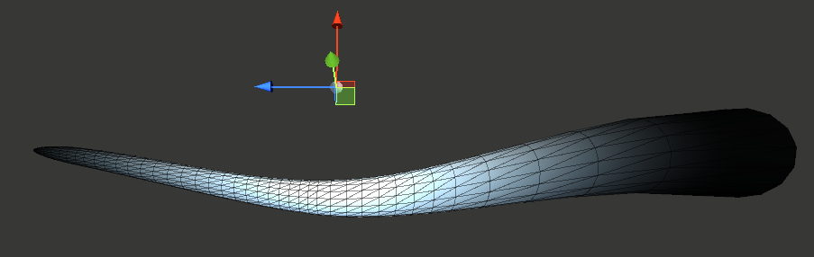
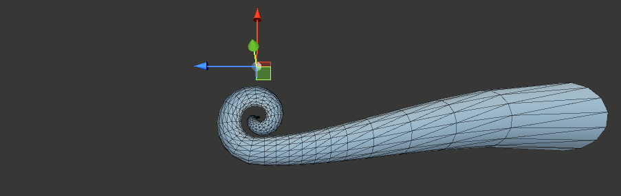
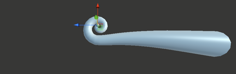
I won’t be going through the steps to create the mesh, as I’m certainly no expert with Blender and I’m sure there are optimisations that can be made here. That said, the image below shows what the mesh I’m using looks like. I basically started with a cylinder (with circles of 16 vertices), then scaled the top and added a bunch of edge loops (Ctrl+R). The plain one is about 700 vertices, which is kinda needed for it to be able to bend properly (as the shader doesn’t do any tessellation). I also added suckers to the mesh which increased the vertex count to around 2.7K.
The orientation and scaling of the mesh may be important if you want to use the same axis & values in my graphs later. It’s aligned along the +Z axis when imported into Unity, with it’s origin at the base of the tentacle. The length is about 20m.
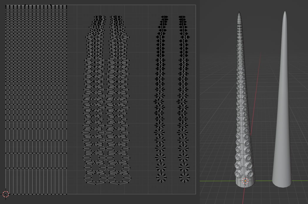
On the right : Tentacle Mesh (and a plain version I used while creating the shader & for images below). On the left : showing the UVs
The UVs are unwrapped using a cylindrical projection. In Blender while in edit mode, highlight all (A) -> UV Mapping (U) -> Cylinder Projection. Then expand the settings in the bottom left, set the Direction to Align to Object, and tick Scale to Bounds.
I’m then scaling it down to about a third of the 0-1 range to leave space for the suckers, which I’ve separated into two parts to be able to mask them in the shader to colour them differently. Though in hindsight it may have made more sense to use vertex colours for that masking.
Also, as Blender likes to export as cm, I’ve unticked the Convert Units option on the model import in Unity, so the mesh looks correct at an object scale of (1,1,1) rather than 100 times that.
Script
The following C# script is applied to the GameObject with the tentacle mesh. It allows us to move another GameObject (e.g. Capsule, or just an empty one) around in our scene, and its position (local to the tentacle object) and scale will be used to set properties on the material.
The shader will use these properties when calculating its displacement. The final result will look like it wraps around that object, like in the twitter gif at the top of this post.
|
|
I’m passing the Material (that will have our tentacle shader on) as a public field, though you could swap this out for a private one and use material = GetComponent<MeshRenderer>().material instead. That would create a material instance, so multiple tentacles can have different interaction points and move independently. (Be sure to Destroy() the material instance too, in the OnDestroy method!)
[ExecuteInEditMode] allows us to preview the tentacle wrapping around objects even when the game is not running.
For testing I use a Capsule as the other GameObject, which I can manually move around in the scene to test the shader. For an actual game I’d likely make that other object empty instead (as in, no components other than the Transform). We could then animate it via an Animation, or use another C# script to sync the position of that empty object with characters when they get close, with a lerp to keep the interaction smooth. There are also some positions which doesn’t work well with the shader (e.g. far out of reach, or behind where the tentacle starts), so we’d want to prevent targetting characters in those areas. That’s a bit beyond this breakdown though.
Shader Graph
In a new Lit Shader Graph, We’ll first create the properties that our script uses, via the Blackboard window :
- Vector3 “_InteractPos”
- Float “_Radius”
(Could alternatively combine these into a Vector4 property and use Swizzle nodes to obtain the “xyz” and “w” parts separately)
In the Node Settings tab of the Graph Inspector window, make sure that the Reference of these properties match the strings used in the C# script.
Vertex Stage
To start, we need to Subtract our InteractPos property from the vertex position (Position node, set to Object space). We only need the Z axis here though, so to obtain that use a Split (B output) or Swizzle node with string set to “b” or “z”.
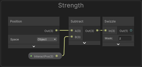
Outputting this temporarily to the Base Color on the Master Stack, then saving the graph (Save Asset in top left), should look like :
(For preview purposes, also put through a Saturate node to clamp colours)
This gives us a value of 0 for vertices near the InteractPos (where the black begins, before this are negative values). It fades to white along the +Z axis as the value increases.
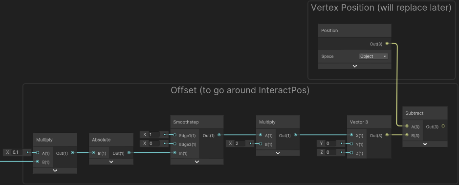
With a bit of scaling (Multiply by 0.1) we can spread the gradient out more and use an Absolute node to flip the negative values into the postive range. I then use a Smoothstep node, which produces a less linear gradient/shape, and at the same time also inverts the result as the Edge1 value is larger (Edge1 is set to 1, Edge2 is set to 0).
We’ll use the result to offset the vertex positions along the -X axis. Multiply by 2 (so we offset by a maximum of 2 units), then put it into the X input on a Vector3 node and Subtract it from the Position node (Object space).
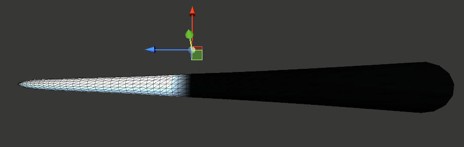
Putting this into the Position port of the Vertex stage of the Master Stack temporarily allows us to preview what this does. The Smoothstep here is also put into the Base Color so we can preview that too. (Note : If you want to do this, attach the fragment stage first or it can lock nodes to vertex-stage and prevent you connecting!)
Previewing the offset. Note how the more white parts offset downwards by a larger amount
Before we can handle any rotation, we first need to clamp the Z positions of vertices beyond the InteractPos. If we don’t do this, then when we rotate the vertices around the InteractPos, they will spiral outwards - which isn’t what we want.
To handle this clamping, we Split the Position node and connect the R and G outputs to the X and Y on a Vector3 node (as we don’t want to alter these axis). For the B output, we put it into a Minimum node, with the other input set to the InteractPos property put into a Swizzle node with “z”.
The output of the Minimum is put into the Z port of the Vector3.
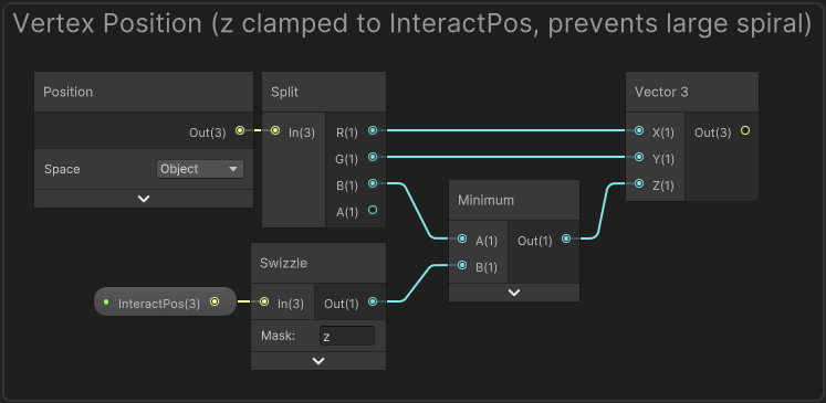
This group will replace the Position node used in the last step (first input of the Subtract node)
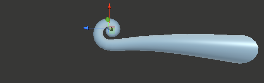
Previewing this in the scene now looks like :
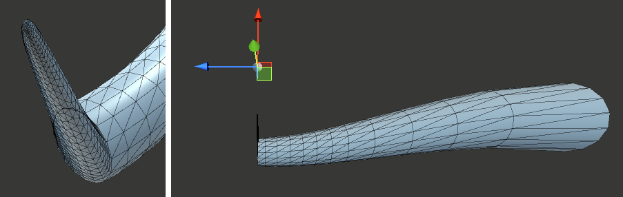
The end of our tentacle might look a bit strange, but since the vertices at the end of the tentacle mesh gets closer to the InteractPos, as we rotate them it will make the resulting tentacle also spiral inwards. (If for some reason we wanted to prevent this, we could replace the Absolute node earlier with a Negate into a Saturate node instead. That would keep it being a circle, but it would also end up passing through itself after a full rotation. This isn’t needed but thought I’d mention it)
We can now handle the rotation,
Use a Swizzle node with “z” on the InteractPos property, and put it into the Z input on a Vector3 node. We also want to connect our Radius property to the X input here, and leave the Y set to 0. We want to rotate our vertices around this position - so think of this Vector3 as the “Center”.
Shader Graph luckily makes it very easy to handle the rotation as there is a Rotate About Axis node. If you’re translating this tutorial into shader code, you can see the generated code for the node on its docs page.
The center of the rotation for this node is always (0,0,0) so we’ll need to temporarily offset (Subtract) by our Center position (that Vector3 we just made). This can then go into the In input on a Rotate About Axis node. We then Add the Center (Vector3 node) back onto this output.
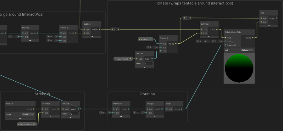
(Click image to view full size in new tab)
For the Axis port, I’m using (1, 1, 0). I thought this produced a nice result as it doesn’t just spiral inwards (like an axis of (0,1,0) would do), but also a bit upwards / diagonally.
For the Rotation input, we’ll take the group from Step 1 (I labelled it “Strength”, the Swizzle node output), put into a Maximum with 0 to clamp any negative values. (The Multiply here is kinda optional. Float node also does nothing here, but I’m using it prevent elbow/redirects turning into Vector4 from the multiply output, due to a bug in Shader Graph with the dynamic port type it uses)
We’re almost there, but the tentacle currently only matches the InteractPos on the Z axis, and ideally we want it to wrap around this position properly.
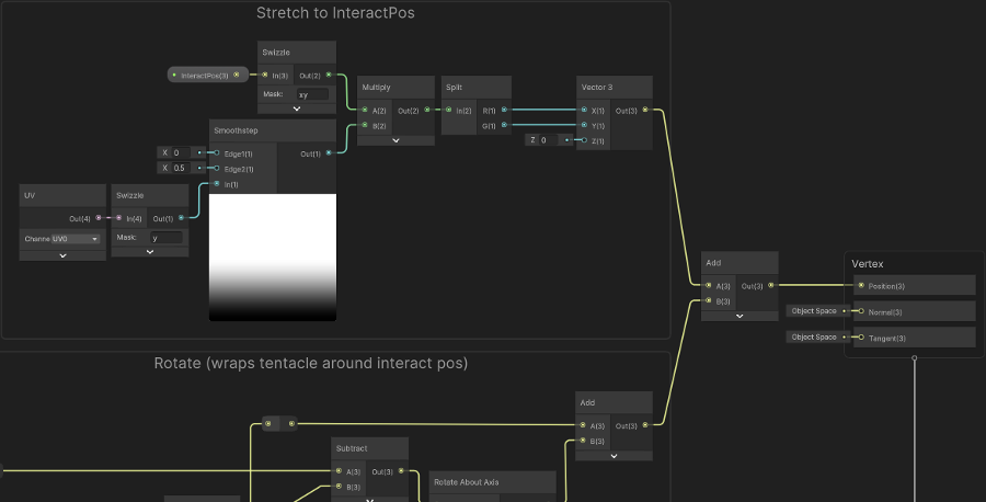
Since the InteractPos input is in object/local space, if we were to Add it to our current result it would shift the origin of the tentacle (which is at (0,0,0)) to the InteractPos. We don’t want to alter the Z coordinate, but that does align the X and Y! Of course this moves the whole tentacle too, so we’ll need to mask it so that it only affects the end.
To handle this masking, we’ll take the Y axis of our UV (by using a Swizzle node, set to “y”, or alternatively Split and use the G output). Put this into a Smoothstep node with an Edge1 of 0 and Edge2 of 0.5. We’ll then Multiply this with the InteractPos (optionally put through a Swizzle with “xy” to obtain the X and Y axis - though not important as the Z is unused anyway).
We then Split the result and connect the R and G outputs to the X and Y inputs on a Vector3 node, leaving the Z coordinate set to 0. Put this into an Add node with the output from our “Rotate” group. This should then go into the Position port on the Vertex stage of the Master Stack.
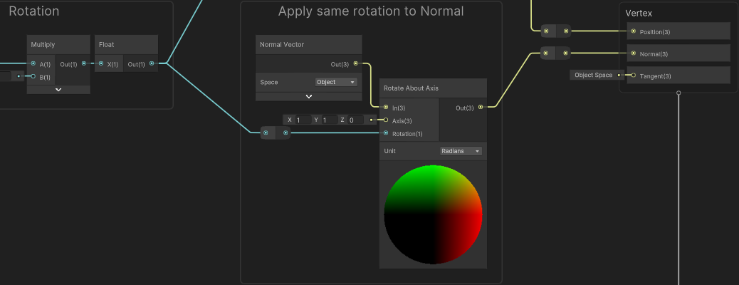
Finally, we should also handle the same rotation on the Normal Vector, so the shading is correct. This involves another Rotate About Axis node, with the same Axis and Rotation inputs, but with the In input set to a Normal Vector node (set to Object space).
Additional Vertex Adjustments
Our tentacle can now wrap around an object, but it is currently quite static when that object isn’t moving. Since it is meant to be more alive, we’ll add some slight scaling - which will make the tentacle look like it grows/shrinks in length a bit. We can also make it pulsate - which I’ve applied to the whole mesh, but it is most visible on the suckers. This involves shifting the vertex position slightly in the direction of the normal vectors.
This will be applied straight after the “Vertex Position (clamped z)” group. (Though you could alternatively handle the pulsating part after everything, but using the rotated normal, if you prefer)
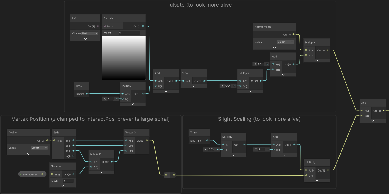
(Click image to view full size in new tab)
For the slight scaling, I’ve used the Sine Time output from the Time node. Multiply by a small amount (e.g. 0.02), then Add 1 and Multiply this with the output from our clamped Vertex Position group.
For the pulsating, I Multiply the Time output from the Time node by 4. Use a Swizzle node with “y” on a UV node and Add these together. Then use a Sine node, Multiply by a small amount (0.04), Add 0.1 and Multiply by the Normal Vector. We can then Add this onto the output after scaling.
The output of this Add node will replace the port that the clamped Vertex Position group was being put into (the first input on the Subtract node in the “Offset” group)
Fragment Stage
This is the graph for the fragment stage if interested. I won’t explain this as it’s only applying some basic colours, and quite specific to the mesh/UVs I’ve used.
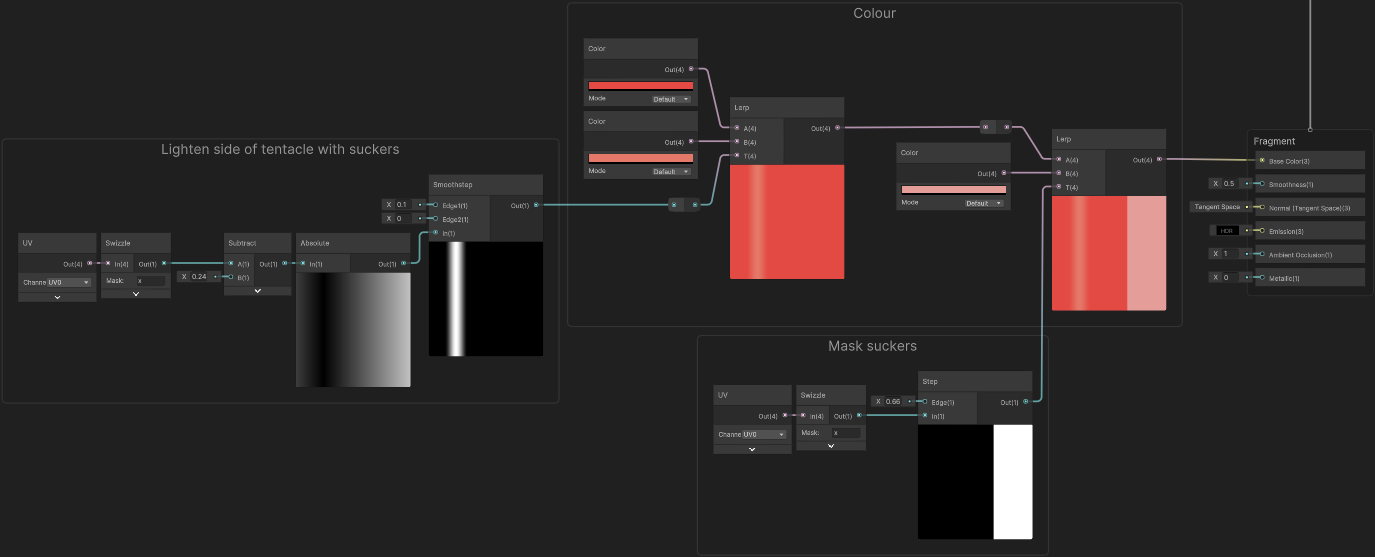
(Click image to view full size in new tab)
Thanks for reading! 😊
If you find this post helpful, please consider sharing it with others / on socials
Donations are also greatly appreciated! 🙏✨
(Keeps this site free from ads and allows me to focus more on tutorials)