Snowglobe Breakdown
Intro
Recently I made this Snowglobe scene (as part of a tech art challenge, with themes “Festive” and “Snow”) in which I used a couple slightly different tools/techniques that I’m used to. I used Unity 2021.3 LTS but may also work in other versions.
There’s especially two parts I’d like to break down :
Snow particles
- Made using a surprisingly simple Visual Effect Graph, mainly thanks to the Collide with Sphere block which allows the particles to remain contained in the glass globe.
- These use a Lit Shader Graph, Opaque surface type.
- I’m using lit here so that the particles receive shadows correctly, but this does also require the normals to be overridden - otherwise (when using mesh normals) the shading changes as the particles rotate, since they are billboarded quads.
- Could alternatively use an Unlit shader if you want, and handle your own custom lighting (perhaps sampling shadows only), or keep particles completely unlit - in which case the regular URP/Unlit shader would probably work.
Glass orb/globe
- Has a more realistic refraction than what I’d typically do. I felt this was important given the snow particles need a medium (i.e. water) to float through, and when filled, the background viewed through should appear flipped.
- It’s still an approximation though. It uses a Reflection Probe that is placed near the globe (preferably at its center, parented to it, and updated regularly - though that would add to the performance cost).
- The refraction was loosely based on an article I found during research - “Refraction in a sphere” (by Sam Driver). In that, they explain the idea behind calculations with some great interactive examples, so it’s definitely a good read.
- In my use case I decided to use a Sphere Mesh rather than defining it fully with maths, which means we don’t need to calculate where the ray enters - as that is the interpolated position given by the Position node. This simplifies things quite a bit.
- I wanted to complete the scene before Christmas, so I’ve also ignored the objects inside the globe - these aren’t affected by the refraction, only the background scene is.
- This uses an Unlit Shader Graph, Transparent surface type and Alpha blending.
(Also, just as a disclaimer - It is possible I have the maths wrong somewhere. If this is the case, feel free to let me know and I’ll update the post. But either way the result looks convincing enough for me! 😉)
Breakdown - Particles
Setup
As mentioned, the snow particles were made using the Visual Effect Graph. In URP this comes as a separate package so must be installed via the Package Manager.
As we need to override the normals (as explained in notes section above) we’ll need a custom shader. I find it easiest to use Shader Graph for this, but we first need to go to Edit → Preferences → Visual Effects and make sure “Improved Shader Graph Generation” and “Experimental Operators/Blocks” are ticked. (In URP 2021.3 LTS at least. Newer versions (or other pipelines) may automatically include Shader Graph support)
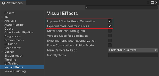
The first setting here adds a Support VFX Graph option to the Graph Settings within Shader Graph (replacing the “VFX Graph” Target which is now deprecated).
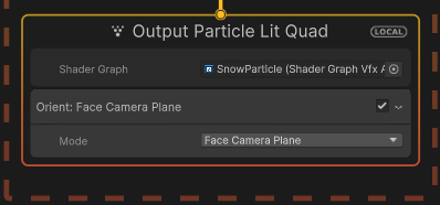
The second setting adds a “Shader Graph” field to the Output Particle Lit Quad context within VFX Graph, which allows us to assign the graph (as when using VFX Graph we don’t use a material!)
Shader Graph
In the Project window somewhere in Assets, right-click and Create → Shader Graph → URP → Lit Shader Graph.
The graph for the particles is very simple. Since we need it to work with VFX Graph make sure you tick the Support VFX Graph option in the Graph Settings (tab under Graph Inspector window). If you don’t see this you may need to configure preferences, see above. If you’re on older versions you may need to use the “VFX Graph” Target instead of the “Universal” one.
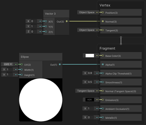
To make them round we should also enable Alpha Clipping. Add an Ellipse node with Width & Height set to 1, then connect it to the Alpha port in the Fragment stage of the Master Stack. We also want to set the Alpha Clip Threshold to 0.9 and Base Color to white.
As mentioned in the intro the particles are billboarded quads, so their shading will change as they rotate. To prevent this I’ve connected a Vector3 node to the Normal port in the Vertex stage of the Master Stack. We can set this to (0, 1, 0).
Visual Effect Graph
In the Project window, right-click and Create → Visual Effects → Visual Effect Graph.
In our Visual Effect Graph we should have 4 contexts : Spawn, then under a System, Initalize Particle, Update Particle and Output Particle Lit Quad. Remove all of the light-grey blocks in these contexts, except the Orient: Face Camera Plane in the final one. Don’t try deleting the dark grey blocks or you’ll end up deleting the context. But if this does happen you can undo, or right-click anywhere in blank space, recreate the context and connect it up.
Spawn
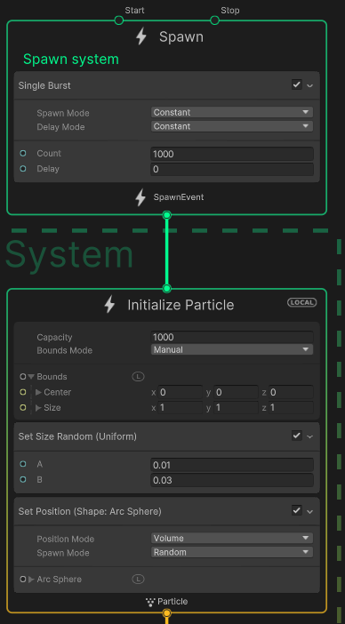
While hovering over the Spawn context, right-click (or press space) and Create Block → Spawn → Single Burst, as we want the snowglobe to start filled with a fixed amount of particles rather than spawning constantly. Set the Count to something like 1000.
Initalize Particle
Under the next context, we should also set the Capacity to the same amount of 1000. I’ve then set the Bounds Mode to Manual with Center as (0,0,0) and Size as (1,1,1). Make sure there’s also a letter L next to Bounds, and not a W (can click to toggle it), as these coordinates should be in local space.
To give the particles slightly different sizes, add a Set Size Random (Uniform) block (easiest to type this in the filter to find it). I’ve set A to 0.01 and B to 0.03.
We also want to make sure the particles spawn inside the sphere rather than all at the same location, so add a Set Position (Shape: Arc Sphere) block. It isn’t too important what Position Mode is used as the particles will fall quickly when we add gravity, but I’ve used Volume.
Update Particle
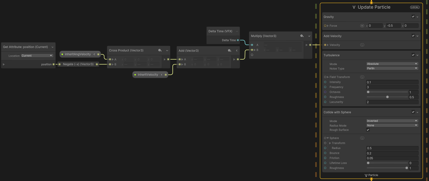
Under this context add a Gravity block. As the snow particles are meant to be suspended in water, I’ve set the Force to (0, -0.5, 0) but you can adjust to whatever feels right. We also want to change this to World space (make sure there’s a W next to the Force, not an L, click to toggle it).
Add a Add Velocity block, we’ll leave this at (0,0,0) for now. It’ll be important in a little bit for making the movement of a Rigidbody component on our snowglobe object affect the particles, but let’s get some other blocks in first.
We want a Turbulence block, which will add some randomness to the movements. This could be Relative or Absolute. If you choose Relative, the Drag should likely be quite low (e.g. 0.1) and it’s important the block comes after the others. I’m also using Perlin noise with an Intensity of 0.1. Frequency of 3, 1 Octave, 0.5 Roughness, and 2 Lacunarity, but feel free to tweak these values!
Finally add a Collide with Sphere block (which is the main reason why I used VFX Graph to create this rather than the Shuriken Particle System component). As the name suggests, it allows our particles to collide with the sides of our glass sphere. Since our particles are inside rather than outside, we want to set the Mode to Inverted. I also found that a Rough Surface was important, with Roughness set to 1, otherwise the particles will just slide around on the glass. Under Sphere, set the Radius to 0.5. For other settings I have Bounce set to 0.2, Friction to 0.05, and Lifetime Loss at 0 (though since we have no Set Lifetime block the particles should have infinite lifetime, so this shouldn’t really matter)
(Click image to view fullscreen)
As seen in the image above I’ve now added a chain of nodes to the Velocity port. This includes two Vector3 properties that have been setup in the Blackboard, “inheritVelocity” and “inheritAngVelocity”.
To support the angular velocity, I’ve added a Get Attribute: position node (set to Current). Put this into a Negate then into the B input on a Cross Product with A set to the inheritAngVelocity property.
To combine with the inheritVelocity, use an Add node. Finally we need to Multiply by Delta Time.
To set the value of these properties, we’ll also need a C# Script. This will be assigned to the same GameObject as the Visual Effect. In this case it’s a child of the Glass Globe object, which contains a Rigidbody component.
|
|
In my case the Rigidbody actually has Kinematic enabled, and is using the following C# Script which makes it match the position & rotation of another empty GameObject - which I’ve animated via the Animation window.
(Though you may also be able to animate the snowglobe directly. During debugging I was originally moving that empty object around manually in the scene view, hence I needed this script)
|
|
Output Particle Lit Quad
Back in the VFX Graph, assign the Shader Graph we created earlier for the particles under the Output Particle Lit Quad context. If you don’t see this Shader Graph field, you need to configure Preferences (see above at the start of the particles breakdown)
You should also have a Orient: Face Camera Plane block here. If you removed it earlier, add it back in.
Breakdown - Globe
Refraction
Moving onto the glass globe, right-click in the Project window and Create → Shader Graph → URP → Unlit Shader Graph. Under the Graph Settings you’ll want to change the Surface Type to Transparent.
In order to handle refractions, there’s a function in HLSL called refract. It has 3 parameters, the ray direction, a normal and a ratio of refractive indices. There isn’t a node for it in Shader Graph (sigh…) but we can create a Custom Function containing it. Given the function body is very short I find it easiest to use the String mode :
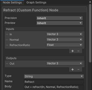
Inputs :
- In (Vector3)
- Normal (Vector3)
- RefractionRatio (Float)
Outputs :
- Out (Vector3)
Name :
- Refract
Body :
Out = refract(In, Normal, RefractionRatio);You will need to copy this node as we’ll need to use the function twice - once on entry of the sphere, and again on exit.
In real life, it would be the light rays that get refracted which then enter the eye, but doing the opposite (simulating a ray for each pixel on our screen going outwards into the scene) is far more efficient. It’s the same concept you’ll find in ray tracing / ray marching. As with a lot of things in shaders, it can be difficult to visualise given each ray will vary, so it’s best to think about one pixel/ray in particular, such as the center of the screen / camera forward vector.
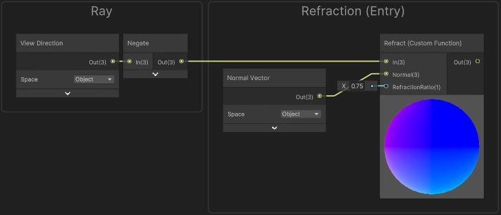
Our rays will start at the camera’s position, and enter the sphere at each fragment’s position. There is a couple ways we could calculate this, but it’s fewer nodes if we use a View Direction node put into a Negate. This’ll go into the In port on our Refract (Custom Function). That’s only the direction part of the ray, but we don’t actually need it’s “origin” right now as there’s no need for a sphere-ray intersection yet. That’s because we already have the point where the ray enters the sphere (Position node. We’ll need this a bit later).
We’ll keep all our calculations in Object space for now. This has some nice benefits, as (0,0,0) is the center of our sphere and so to calculate the normal vector at any point on the sphere it’s simply the position of that point normalised! The Refract (Custom Function) also needs the normal at the entry position, but in this case we can use the Normal Vector node.
For the RefractionRatio (ratio of refractive indices) we’ll need to know the Refractive Index of the materials we’re working with, which we can just search for online; such as this list on Wikipedia. Air is basically 1, Glass around 1.5, and Water around 1.33.
While we could do 4 refraction calculations (air → glass → water → glass → air), as the glass is quite thin it doesn’t actually affect the resulting ray all that much (I confirmed this by redoing the calculations in C# and drawing debug gizmos). So while less accurate, we can ignore it and treat our sphere as a ball of water (air → water → air).
The ratio needs to be entry/exit, so 1/1.33, which is about 0.75.
When the refracted ray exits the sphere it will be refracted again so we’ll need the second Refract (Custom Function). The RefractionRatio for this is 1.33/1, so just 1.33.
We also need to know the normal (which would be the exit position normalised, then negated as we need it pointing inside the sphere. The next section goes over this)
Sphere Exit Point
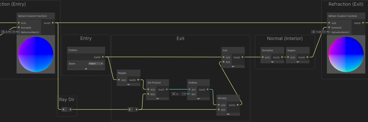
To calculate the position of the Exit point, we’ll need a function to handle a ray-sphere intersection. Well, as we already have the Entry point we can actually simplify things… We’ll only need :
- Ray Entry, Position node
- Ray Direction, which is the output from our first Refract (Custom Function)
- Sphere Center Position, which is just (0,0,0) as we’re working in Object space.
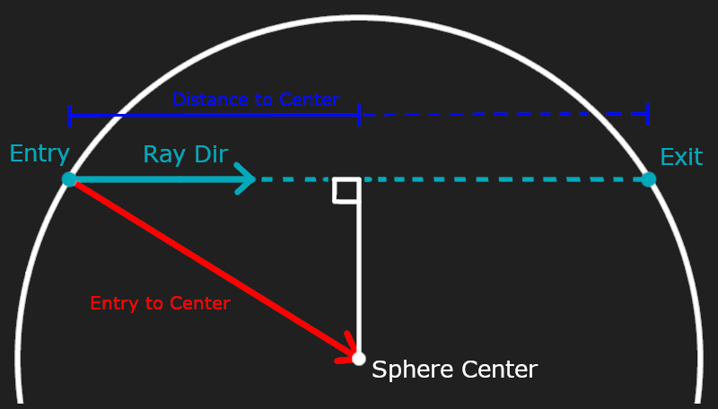
The idea is, we can create a vector from the Entry point to the Sphere Center, and project this onto the Ray Direction. As this direction is already a unit vector (normalised), it’s just a Dot Product!
That’ll give us the distance to the Ray Center, which we can double to obtain the distance to the Exit. To get the actual position of the Exit point, it’s then Entry + Ray Dir * DistanceToExit.
In terms of nodes, we need a Position node (Object space). Since the sphere center is (0,0,0) we can put this into a Negate node to give us the vector to center. Then put this into the A port on a Dot Product with B set to the Ray Direction (result from the first Refract (Custom Function))
Multiply by 2, then Multiply by the Ray Direction and Add the Position node.
With our exit point calculated, we’ll Normalize it to calculate the normal on the sphere at that point. Since we are inside the sphere we need to Negate, then put it into the Normal input on our second Refract (Custom Function).
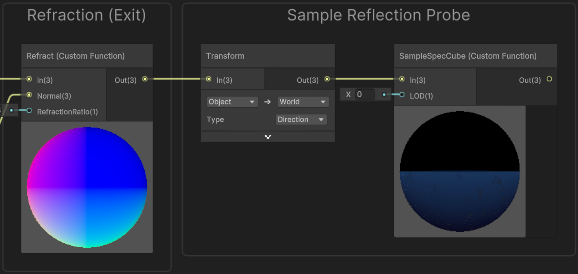
Sample Cubemap
We now have the final refracted ray, and can use it to sample our reflection probe. We first need to use a Transform node from Object to World space, using Direction mode. We’ll then need to create another Custom Function (String mode) :
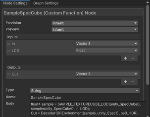
Inputs :
- In (Vector3)
- LOD (Float)
Outputs :
- Out (Vector3)
Name :
- SampleSpecCube
Body :
float4 sample = SAMPLE_TEXTURECUBE_LOD(unity_SpecCube0, samplerunity_SpecCube0, In, LOD);
Out = DecodeHDREnvironment(sample, unity_SpecCube0_HDR);
Put our transformed ray into the In port. We’ll leave the LOD at 0 so we’re sampling the highest possible resolution but you could use a slightly higher value to fake some blurriness.
Interior
As I was trying to make a Snowglobe, I wanted objects to appear inside the sphere too. In order to handle this I felt rendering those objects to a separate buffer (Temporary Render Texture) was best, as we can then sample that in our shader and it keeps the objects always rendering inside the globe. It also gives us the option to distort that texture to fake some interior refraction too (though I didn’t get around to trying this).
You could alternatively use Stencil operations (via Overrides on a RenderObjects feature since Shader Graph doesn’t allow access to them).
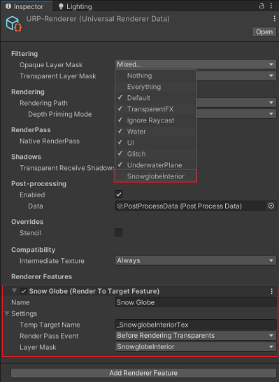
We’ll put any interior GameObjects on a specific Layer, named something like “SnowglobeInterior”. To render this layer to another buffer we could use another Camera, but I felt it was easier to use a URP Custom Renderer Feature (intended for Unity 2021.3 LTS. If you’re in newer versions you may want to rewrite this with an RTHandle) :
|
|
Note that we use Color.clear when clearing the temporary render texture. This is so that the background will be transparent (alpha = 0), so we can blend correctly in the shader.
This feature will be passing the texture into the global shader property. We’ll need to assign it to the Forward/Universal Renderer Asset. Set the Temp Target Name to something like "_SnowglobeInteriorTex". For the Render Pass Event I’ve used Before Rendering Transparents. Set the LayerMask to the SnowglobeInterior Layer and also be sure to remove that layer from the Opaque Layer Mask and Transparent Layer Mask (as we don’t want objects on this layer to render normally on cameras).
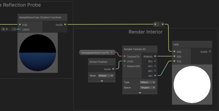
Back in the Shader Graph, create a Texture2D property in the Blackboard named “SnowglobeInteriorTex”. In the node settings while the property is selected, the Reference should be the same as the tempTargetName in the feature settings ("_SnowglobeInteriorTex", if not already that). As it should be a global shader property, we also need to untick the Exposed option.
Use a Sample Texture 2D node with this texture property, and a Screen Position node in the UV port. The RGBA result from this sample should go into the B port on a Lerp node, with the A input set to the result from our refraction (SampleSpecCube (Custom Function)). The A output from the sample should go into the T input. This is basically replicating an alpha blend.
Reflection
To really look like glass we should also add reflections. It’s much easier to let Shader Graph do most of the work here - by using a Reflection Probe node. This takes in the View Direction and Normal Vector, which should both be in World space this time. We’ll leave the LOD at 0.
We can use this in the B input of a Lerp node with A set to our previous result (combining refraction & interior) and T set to a Fresnel Effect node. You can adjust the Power or add a Float property here if you want, but I’ve set it to 2.
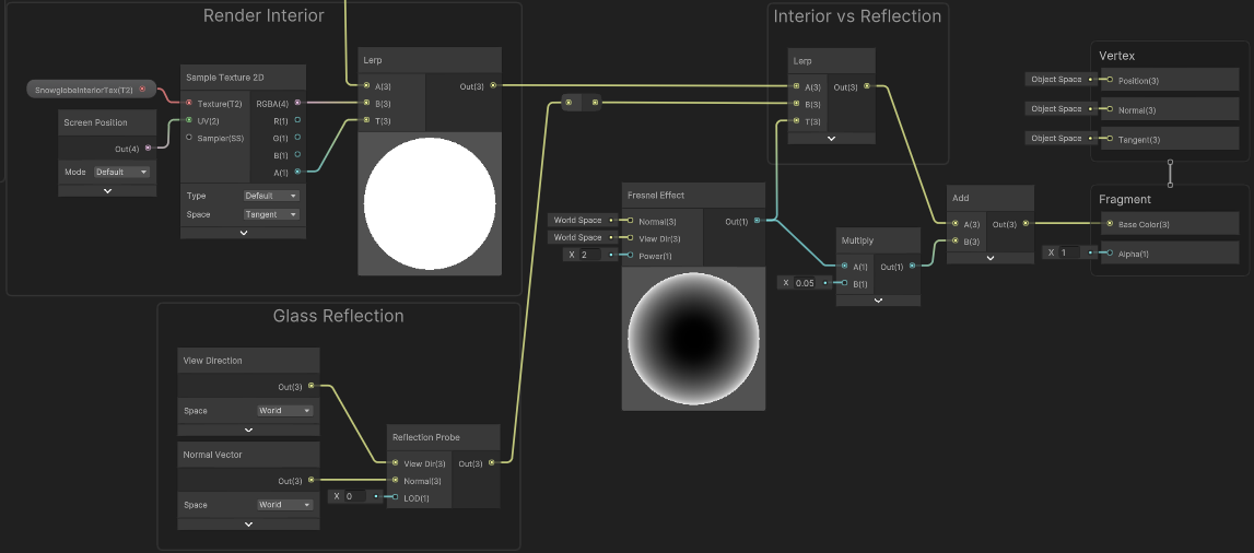
As I want to be able to see the glass better, I’m also tinting the result using that fresnel slightly but this isn’t really accurate to real life. I’m also ignoring any reflections from rays bouncing around the inside of the sphere but if you’re interested in that Sam Driver’s article includes a section going over that which is pretty neat.
Overall I’m pretty happy with result. It’s a bit late now, but Merry Christmas!~ 🎄☃️😉
Thanks for reading! 😊
If you find this post helpful, please consider sharing it with others / on socials
Donations are also greatly appreciated! 🙏✨
(Keeps this site free from ads and allows me to focus more on tutorials)