Liquid Shader Breakdown
Intro
This liquid shader is based on discarding pixels that are above a certain Y position and rendering the back faces of the mesh in order to fake the top surface of the liquid.
Based on Minions Art’s liquid shader, also see their shadergraph version here.
Notes
- Models that use this technique need to have a pivot roughly in their center of mass, in order for the liquid distribution to look correct.
- I’m using an Unlit graph. If you want lit, note that since the liquid surface is faked with back faces they won’t have the correct normals to produce the correct lighting. You’ll need to override the normals for the backfaces (using the Is Front Face and Branch nodes), maybe setting them to a Vector3 (0, 1, 0) (or passing a Vector3 property in) when False, and use the regular Normal Vector when True.
- If you want to apply a texture to the fake top face, you’ll need to calculate the correct UVs which requires the shader to know the normal and tangent of the plane that is used to clip the mesh (won’t work if additional sine movement is involved). Remy (from Unity) has an amazing CrossSection example that does this.
- Glass shader not included.
Breakdown
First we use a Position node to obtain the pixel/fragment’s position. We need to use World space so that the liquid doesn’t rotate with the model, which it would do if we used object space.
With this position we could discard all the pixels that are in the positive Y direction (upwards, where Y > 0). However, doing this with the world position means the liquid height will not move if the object is moved, and it will become completely submerged or invisible if it’s moved too far below or above the liquid height level. To fix this, we need to first Subtract the object’s world space position which can be obtained via the Position output on the Object node.
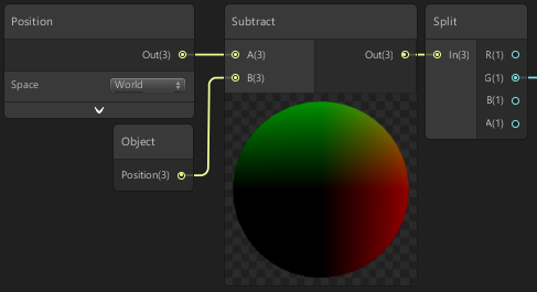
So we can extract the Y axis from our result, we’ll put it into a Split node. It is labelled as RGBA, but this is the same as XYZW.
For now, we will take the Y/G value, and plug it into the Edge input of a Step node. This has two inputs and returns 1 if the In input is greater than or equal to the Edge, otherwise it returns 0. I will leave the other input as 0, but you could also connect a Vector1 property here so you can change the liquid height from outside of the shader. The output of this step node will go into the Alpha input on the Master node.
We can then use a value of 0.5 for the AlphaClipThreshold input on the Master node, which tells the shader to discard pixels that are below this threshold. We should now see that pixels above the pivot of our object are discarded, but there is no top surface yet. There’s no way to add actual geometry to this surface but we can fake it by rendering back faces. To do this, click the cog icon on the top right of the Master node and tick the Two Sided tickbox. (Note, in URP v10+ this can probably be found in the Graph’s Inspector window instead)
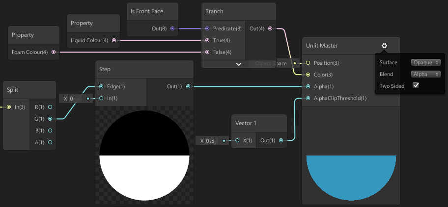
Now that there is a top surface we should change the colours so we can see the effect better. We’ll use a Branch node with the Predicate set to use the Is Front Face node. This is a Boolean value as shown by the (B) and purple connections. It should be fairly self-explanatory what these nodes do – it’s basically an if statement based on whether it is a front face or not. If it is a front face, it will use the True input as the output and if it’s a back face it will use the False value instead.
We’ll plug two Color nodes into the True and False inputs. The true one being the liquid colour, and the false the top surface/froth/foam colour. We could also convert these to Color properties, so it is possible to access them outside of the shader and create multiple materials with different colours. To do this we can either right-click on a Color node and select Convert To Property, or click the plus icon in the Blackboard, select Color and then drag the newly added property on that list into the graph.
The output of the Branch will then connect to the Color input on the Master node.
To improve the effect, I added a level of foam onto the side of the front faces. We can do this by adding another Step node (using the same input as the other one), but offset the Edge input by a small amount. I’m using 0.05 for this, but it might again be a good idea to use a Vector1 property here instead, so you can change the foam height from outside of the shader.
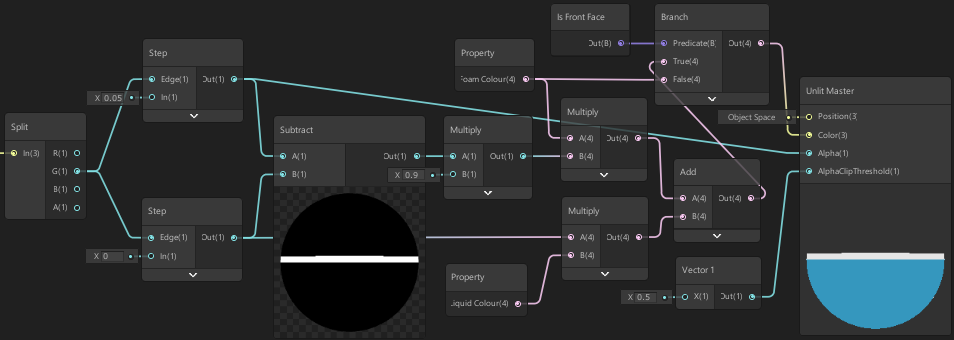
Multiply the lower Step output with the liquid colour and put this into an Add node, leaving one of the inputs empty for now. Then we can Subtract the lower step from the higher step to obtain our foam level, and Multiply the output by 0.9 - so it isn’t exactly the same colour as the top surface. We can then Multiply it again by the foam colour and use this as the other input on that Add node mentioned before. The output of that replaces the True input of the Branch node we set up earlier.
That’s pretty much the effect. I also added a little Sine movement to the liquid height by offsetting the Y/G value from the Split node using the R/X component, a Time node and a few maths based nodes like this:
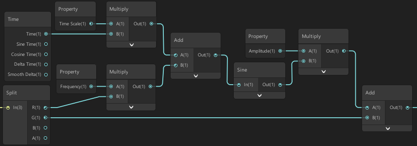
The Frequency and Time Scale properties are set to 1 but it is useful to have them there if you want to adjust the effect slightly, and the Amplitude is set to 0.05. The output of the Add on the right replaces the input into the Step nodes from earlier.
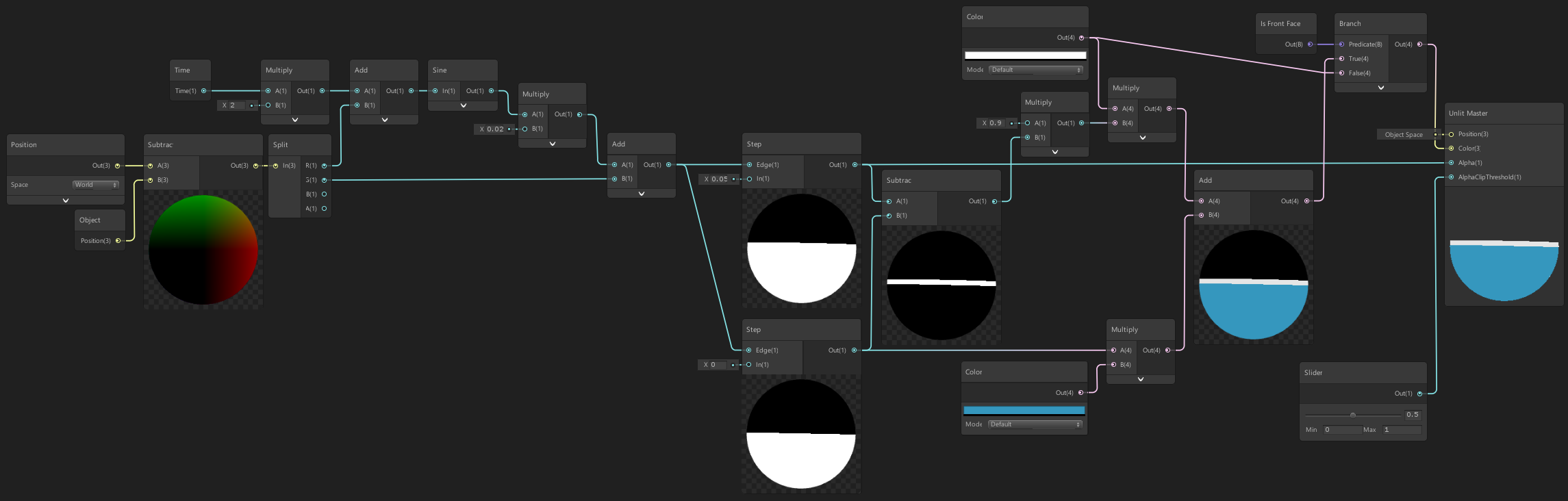
Here’s a final image showing the entire graph:
Thanks for reading! 😊
If you find this post helpful, please consider sharing it with others / on socials
Donations are also greatly appreciated! 🙏✨
(Keeps this site free from ads and allows me to focus more on tutorials)