Hologram Shader Breakdown
Intro
This hologram shader is based on using sine and/or fraction (known as frac() in HLSL) functions on the world space Y position in order to produce a repeating set of horizontal lines, similar to scanlines. With transparency, additive blending, HDR colour tint and a Fresnel effect, this produces a fairly simple but effective hologram effect. I’ll also be sampling a texture with some added distortion and glitching effects to make the hologram shader more interesting when applied to quads.
Notes
- This is an Unlit shader, using Transparent surface mode and Additive blending. (Click the cog on the Master node to set these)
- The shader can be applied to both 3D meshes and quads (the planet in the image for example uses a sphere while the other objects are quads, most textured with a circle/ring texture). I will also go through some additional distortion and glitch effects but they will only really look good for textured quads. You could achieve similar effects in 3D by offsetting vertices, but I won’t be discussing that in this post.
- It looks best when using HDR colours and Bloom post processing. Note that bloom can be quite expensive though, especially when targetting mobile platforms.
Breakdown
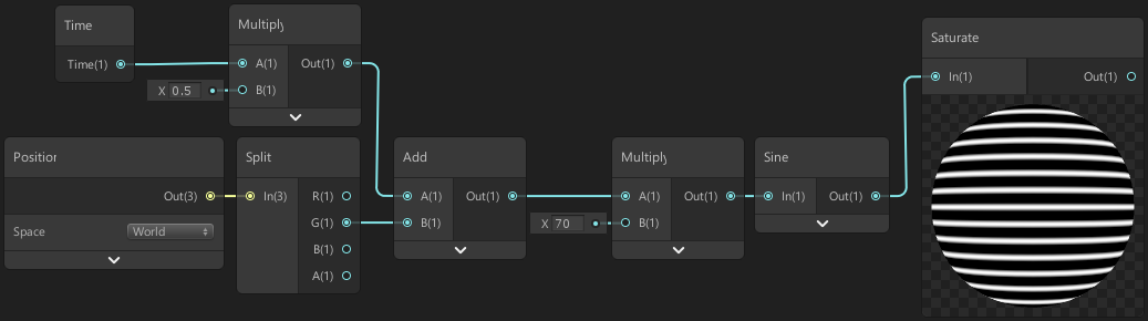
First we use a Position node to obtain the pixel/fragment position in World space. (You could also use Object space if you want to be able to rotate the scanline effect, but I want to always keep them aligned to the Y axis regardless of rotation, so I’ll be using world space. If you use object space you should also Multiply this by the objects scale from the Object node so it doesn’t stretch the effect).
Take the output of the Position and put this into a Split node. In order to create horizontal lines we’ll take the Y coordinate of our position (from the G output) and Multiply this by a vertical scaling value (e.g. 70). Then put this into a Sine node (or Cosine node as we don’t care if it is offset slightly). Since this returns values between -1 and 1 we’ll put this into a Saturate node so we clamp the values between 0 and 1. We can change the scaling value if we want more/less lines.
To make this animated we can use the Time output from the Time node and Multiply this by a value to control the scroll speed (e.g. 0.5). We’ll then put this into an Add node with the Y/G output of the Split to offset it before replacing it with the input into the Multiply node we created earlier (the one that goes into the Sine).
Another way of producing a similar scanline effect is to use the Fraction node. Instead of being smooth like a sine wave this produces a sawtooth wave with harsh transitions between the lines, as values to go from 0 to 1 and straight back to 0 again. This is because the node returns the fractional, or decimal, part of the value. Or put another way, it removes the integer part of the number. e.g. 3.26 would become 0.26.
We can use both these together to make our hologram shader more interesting. We can either create new nodes or just copy-paste the existing Multiply → Add → Multiply nodes we have so far, then put the output of the last multiply into a Fraction node. Note that we don’t need the Saturate node for this part as the fraction output is already between 0 and 1.
I’m setting the scroll speed and vertical scaling both to 1. While this means these Multiply nodes don’t do anything, I prefer to keep them as it allows us to adjust the effect if needed. (As a note, you may notice that when using the same value to scale the Sine and Fraction nodes they output different amount of horizontal lines. This is due to the sine function taking an input in radians (in terms of Pi). We could multiply by 2*Pi before putting a value into the Sine node to ensure the scaling is the same for both, but this isn’t too important).
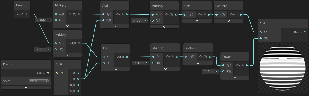
I’m also going to put the output of that Fraction node into a Power node with a value of 2 to make it less linear and then take the output of this and the Sine node from before and Add them together.
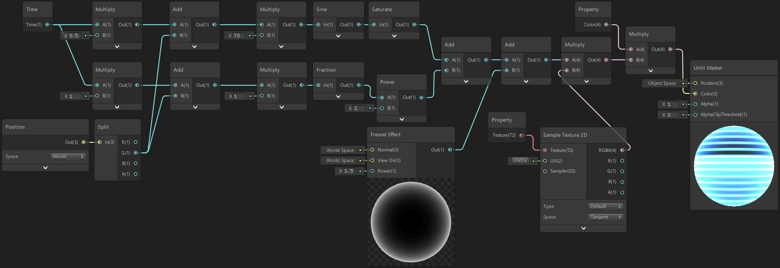
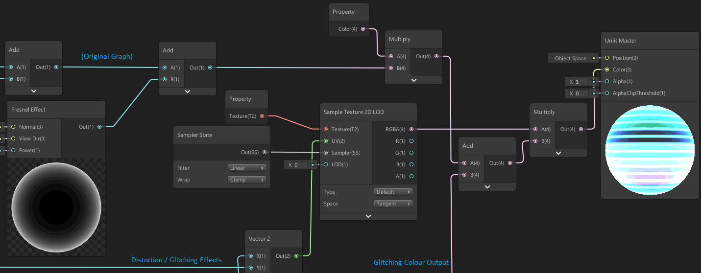
Before we add some colour, we can also apply a rim or fresnel effect which improves the hologram effect for 3D objects. Create a Fresnel Effect node and Add its output with our current result.
A good way of applying colour is by using a texture and colour to tint it. By using this combination we can use a black & white mask texture to get a specific shape, and then colour it using the tint colour, or just leave the tint colour as white and display a texture normally.
To do this Multiply the output from the previous Add node with the RGBA output from a Sample Texture 2D node. We’ll then take the output of that and Multiply again by a Color property (use the blackboard in the top left to create this, or create a Color node, right-click and Convert To Property). I’m using a colour property with HDR mode and an Intensity of 2 along with some post processing Bloom to make the effect ‘glow’ more.
Finally put the output of that into the Color input on the Master node and click the cog to change it to Transparent and use Additive blending if you haven’t done so already.
Since creating this hologram shader I’ve also added some additional parts to improve the effect, explained below.
Additional Effects
Distortion
To improve the effect I added a horizontal distortion effect to the texture sampling. This is fairly simple to do, we just need to offset the UV coordinates going into the Sample Texture 2D node. (Note, this will only work when applying the shader to a quad. If you want a 3D object distortion approach you would need to manipulate vertex positions instead, or possibly use a post-processing based distortion effect (similar to heat distortion?), both of which I’m not going into in this post).
In order to create our horizontal distortion we first need to create a UV node and Split it. We can then use the Y/G output in order to create some noise which we will use to offset the X/R output. Since we’re basing the noise off this vertical Y/G value pixels going horizontally won’t change, which is what we need in order to offset that entire line of the texture uniformly. To help adjust our distortion we’ll also use a few Vector1 properties along the way. (To create these use the plus button on the shadergraph blackboard or create a Vector1 node, right-click, and select Convert To Property. To rename it, right-click the property in the blackboard).
First we’ll Multiply the Y/G output with a Vector1 property named Distortion Scale, then put this into the first input on an Add node. Create a Time node and Multiply the Time output with another Vector1 property, named Distortion Scroll Speed. Then put that into the second input in that Add node from a second ago.
We’ll then put the output from that Add node into a Gradient Noise node, using 10 as the noise Scale input. (For a less wobbly distortion, we could instead use a Random Range node to generate random noise, with a Multiply and Floor node before it to control the height of each line).
Since this noise returns a value between 0 and 1 we will Subtract 0.5, so our distortion will be centered. Then Multiply by 0.1, and Multiply again by a Vector1 property named Distortion Strength. (Note that I’m just multiplying by 0.1 so that our strength value is more reasonable, as without it, a value of 1 would distort the texture by a maximum of half of itself (since our noise is between -0.5 and 0.5), which is quite a lot of distortion).
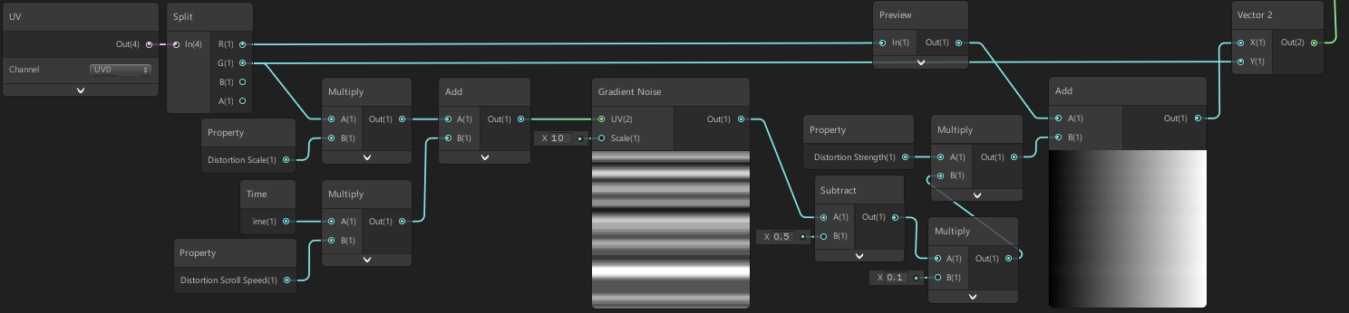
We’ll then Add our output with the X/R output, from the Split earlier, and put this into the X input on a Vector2 node and put the Y/G output into the Y input. The image above shows how I’ve arranged all of this. The output of that can then be put into the UV input on the Sample Texture 2D node from earlier.
Glitching
Another effect we could add is a glitching effect, as seen in the tweet above. (Again note, this will only work when applying the shader to a quad).
We first need to create a UV node and Split it. (If you did the distortion effect above you can use the split from that one instead).
We’ll be offsetting our Y/G output, but rather than making it scroll downwards I want the glitching effect to be more static (not moving), but still animated so that it changes over time. If we put the Time output from a Time node into a Multiply and then into a Floor node it will keep the same value until it increases past the next integer value (which is each second, since the time output is measured in seconds). By changing the value in the Multiply we can scale this, so it reaches the next integer slower or faster.
We’ll take the output of our Floor node and the Y/G output from our Split and Add them together. I’m then going to Multiply it by 10 and put the output into a Random Range node to generate random values between a Min and Max value of -1 and 1.
These random values will be how much offset to apply, before we use this though it would be useful to control the glitching more. We can probably do this in a number of ways, but I put the random output into an Absolute node, and then into the Edge input on a Step node. (Returns the absolute value so everything is in the positive range, above 0. So values like -0.5 become 0.5 instead. The step then returns 1 if the In input is greater than or equal to the edge input, otherwise it returns 0).
We’ll put a Glitch Amount Vector1 property into the second input of the Step node to control the amount of glitching that will get past the step. (A value of 0 will allow no glitching through, 0.5 half of it, while 1 will allow all of it). We can then Multiply our random input by this step output, Multiply by 0.1 and Multiply again by Glitch Strength Vector1 property to control the strength of our glitching effect.
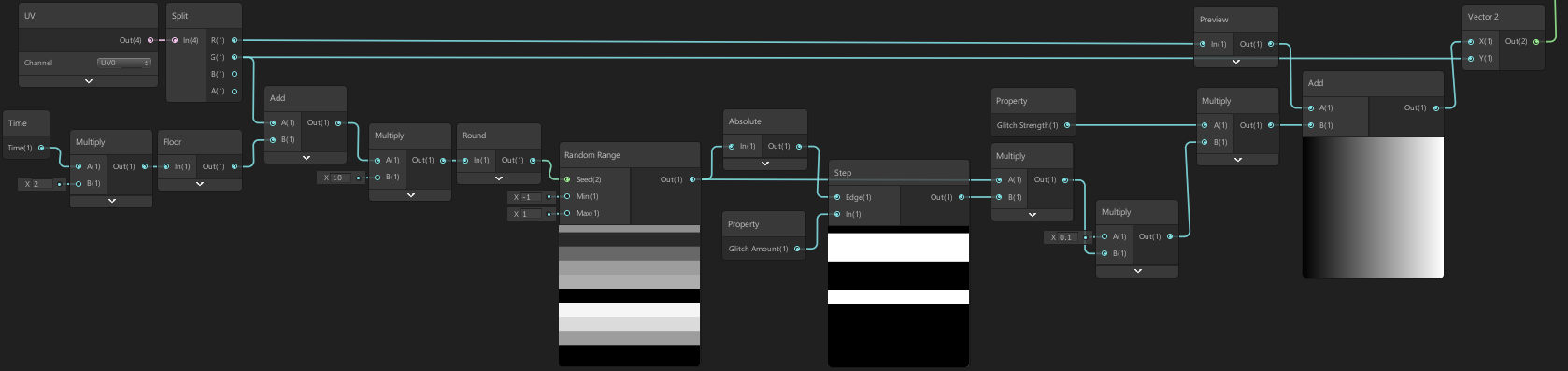
Add the output with the X/R output, from the Split earlier, (or with the Add output from the previous distortion effect if you did that. Note the image above does not include this). Then put this into the X input on a Vector2 node and put the Y/G output into the Y input. The image above shows how I’ve arranged all of this.
The output of that Vector2 node can then be put into the UV input on the Sample Texture 2D node from earlier. You may also want to switch this out for a Sample Texture 2D LOD node with a LOD value of 0 as you might see some unintentional glitchy parts between the lines, (unless you think this adds to the glitch effect I guess).
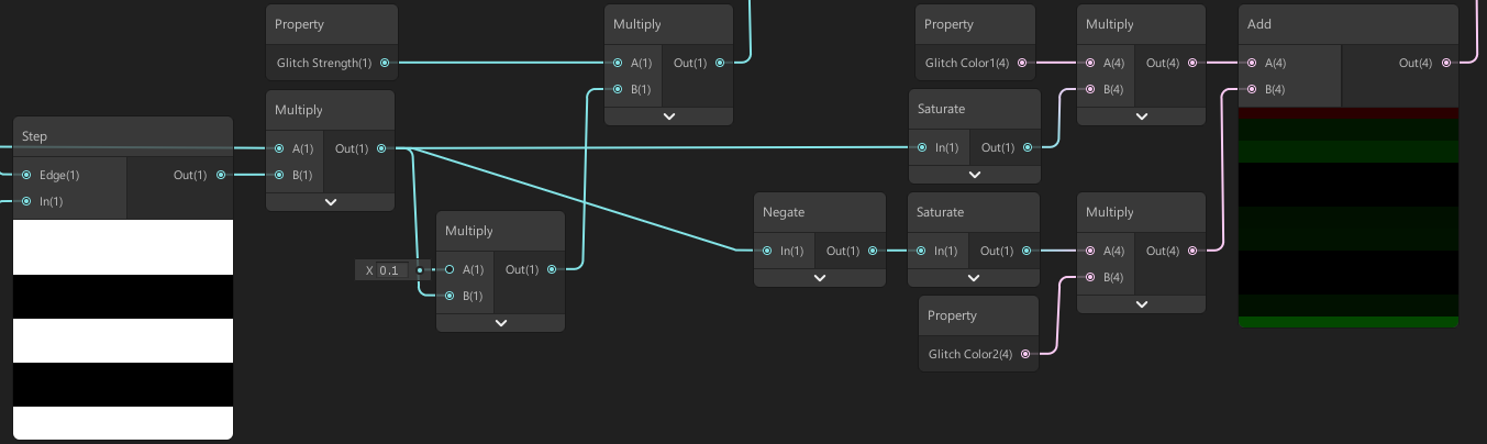
We can also make the glitching change the colour of the effect. You could use a Hue node to offset the colour, but I found this gave too much variation. Instead, I took the Multiply output (the one including the Random Range and Step inputs). Since this is between -1 and 1 we can colour the positive offsets and negative offsets differently. I simply use a Saturate node to clamp values between 0 and 1 and then Multiply by a red Color property, and do this again but with a Negate node and green Color property. I then Add these two outputs together, as seen in the image below.
We can then Add this to our previous colour that went into the Master node, but before the Sample Texture 2D LOD node to ensure it is masked correctly. You may need to rearrange the nodes a little, but it should look something like below.
Thanks for reading! 😊
If you find this post helpful, please consider sharing it with others / on socials
Donations are also greatly appreciated! 🙏✨
(Keeps this site free from ads and allows me to focus more on tutorials)