Holofoil Card Shader Breakdown
Intro
Lately I’ve been experimenting a bit with holographic foil shader effects. The tweet above includes the final result, but you can also see some of the experiments I did in this tweet thread.
The shader uses the Tangent Space View Direction vector, which is commonly used for parallax effects. The vector is distorted using a texture sample, then used to sample a repeating rainbow texture (optionally with some gaps, as shown below) which provides a nice holofoil effect (or at least a stylised version of it, this isn’t meant to replicate it accurately).
We can then mask this over various parts of the card, either to remove it completely or provide different intensities as we don’t want to make the card itself unreadable. Some parts being brighter than others also produces the illusion that they are more reflective and especially looks good with Bloom Post Processing enabled (though that can be very expensive if targeting mobile platforms).
The rainbow gradient could also be generated procedurally but I felt using a texture was much easier and provided more control over the resulting look as it can be swapped out for other gradients too. If you want to look into it though, Alan Zucconi’s Improving the Rainbow article (and it’s part 2) is a good resource.
Notes
- This is an Unlit shader using Opaque surface mode (for the main card at least. The window is using a separate graph with the same node setup, but with Transparent & Additive blending. I’d recommend putting the Holofoil effect in a Sub Graph so it can be shared between both). It could also work in a Lit/PBR graph, though you would then likely want the holofoil effects to be used in the Emission port.
- Also using Post Processing in tweet gif/videos (ACES Tonemapping & Bloom). This isn’t required though.
Breakdown
Holographic Foil
Obtaining the View Direction in Tangent space is extremely easy in Shader Graph as it’s one of the space options on the node. If you output this temporarily to the Base Color port on the Master Stack (or Node if prior to v10) and assign it to a quad in the scene, you’ll see that it moves with the camera. These coordinates are almost perfect for the effect we want, but we should Negate them so the rainbow texture doesn’t get flipped.
With most parallax effects, it’s common to use this to offset existing UV coordinates (UV - viewDirTS). While we could still do that here, I felt it wasn’t needed. If you’re interested in including that it would kinda “delay” the coordinates from matching where our camera is, if that makes sense.
We want to (optionally) distort the coordinates to create the interesting holographic foil patterns some trading cards have. We can use a texture to control these patterns so need the Sample Texture 2D node using a Texture2D property, and use a Tiling And Offset to alter the UVs. We’ll use a Vector4 property and Split and recombine them into Vector2 nodes for the Tiling and Offset inputs, allowing us to easily control those settings from the material inspector.
As my card mesh uses the UV0 channel for other data (as I’ll explain in the next section), I’m also projecting the texture onto the mesh by using the Position node in Object space (X & Y axis) as the UVs instead.
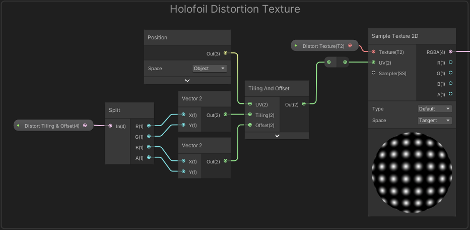
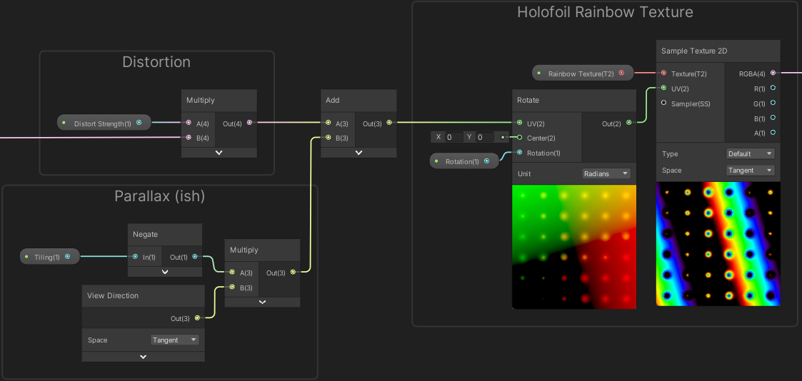
I’m using a few greyscale textures currently for these distortion patterns, which basically results in pushing the coordinates towards the top right a little bit. This works well as long as the rainbow texture isn’t also aligned with that direction but we could also provide some rotation with the Rotate node after the texture sample to push the distortion in a different direction. Alternatively we could use textures that store directions themselves similar to Flow maps or Bump/Normal maps (in which case we’d also have to remap the texture sample output, e.g. Subtract 0.5).
The RGBA output from the Sample Texture 2D is multiplied with a “Distortion Strength” Float property and the Tangent space View Direction is also multiplied with a “Tiling” Float property. These two outputs are then added together and put into a Rotate node (allowing us to optionally rotate the whole foil effect), then into the UV input on another Sample Texture 2D node which samples the rainbow texture.
It’s a relatively simple graph but with the right textures this can produce some really nice holofoil effects. Next we’ll look at masking this to specific parts of the card.
Masking
In order to mask the Holofoil effect to specific parts of the card, we first need a way to separate each part. I’d also like to be able to control the strength of the holofoil effect for each part rather than toggling it completely.
This could be done with an additional texture, i.e. using the separate RGB channels for each part of the card. In the graph we could then use the Sample Texture 2D node and the R, G, B outputs give us the masks. (If 4 masks is needed the alpha channel can be used, though might need to be inverted in the texture as some programs don’t allow storing colour in areas with 0 alpha. Can then access it with One Minus the A output to invert it back).
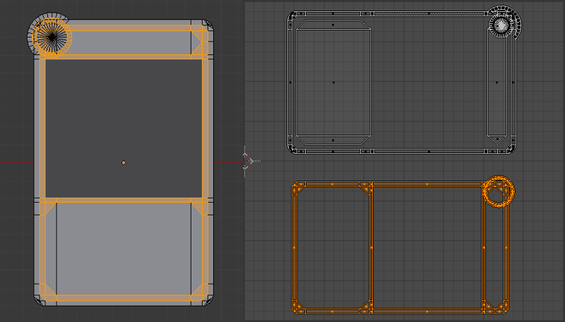
Avoiding another texture sample would be cheaper so we could alternatively use Vertex Colors (though you would then have to separate those vertices you want to paint so the parts don’t blend), or use a specific UV Mapping. For example my card has two parts so we can have the vertical axis from 1 to 0.5 be the main body of the card, while 0.5 to 0 is the shiny edge/border (or vice versa).
We can then obtain the mask in the shader by using the UV node, Split and use a Step node on the Y/G axis with a value of 0.5. And One Minus to obtain the mask for the other half.
If we needed more sections this can be extended by splitting the UV into more sections and we could combine it with the X axis too. If you prefer, the Step nodes could also be replaced with Comparsion which allows us to use the logic nodes (e.g. And, Or) and Branch with values of 0 and 1 to then obtain a mask.
For each mask we can provide a Float property (or store them as a Vector property). We Multiply each mask by the property, then Add the results together. Rather than multiplying each float separately, it’s easier (and likely more efficent) to combine them into a Vector4 as shown below. We finally Multiply by the Holofoil result and output it to the Base Color on the Master Stack (or perhaps Emission if using a Lit Graph).
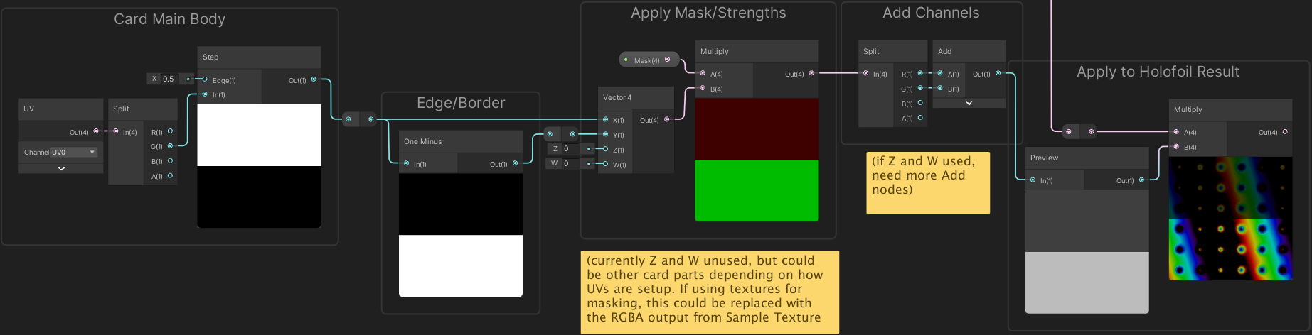
With this we can now adjust the (X and Y) values of our Mask property to control the strength of the holofoil effect on the main card vs edge/border. Using values over 1 also allows us to increase the intensity of the effect, which as mentioned in the introduction produces the illusion that it is more reflective. It especially looks good with HDR enabled on the URP Asset and using Bloom in the global Post Processing Volume (though note it can be very expensive if targeting mobile platforms).
Stencil Window
The card includes a rectangular window where you’d typically put a creature/item/etc, but rather than using a 2D texture, I’m using a 3D model - though I’m not that good with modelling so just using a placeholder cube for now. This sort of effect works best with a single card.
We only want the model to appear when viewed through the card, which we can do using the Stencil buffer. If you aren’t familiar, it’s an extra 8 bits that is included alongside the 24-bit depth buffer. We can write and test against values in the buffer (using an integer from 0 to 255). If the test fails it will discard fragments/pixels before they are rendered.
The card mesh that I’m using is separated into two meshes (and two separate GameObjects / MeshRenderers). It includes a hole where the window is located (allowing us to see the model behind it), and we have a separate quad mesh to render the window itself.
Shader Graph currently doesn’t have access to setting Stencil values, but we can instead assign two materials to the window MeshRenderer : One will draw the window into the stencil buffer only (shader code shown below), and the other material can use a similar Shader Graph to the Holofoil effect above but using Transparent surface mode and Additive blending (Assuming you want the effect to show on the window).
|
|
This shader makes sure the window gets drawn to the Stencil buffer using a reference (defaults to 2 in this case). We then need to draw the object that will be inside our card using the same reference with the Equal comparison. When drawing the fragment/pixel if the reference is not equal to 2 it will be discarded (so the object is not visible unless viewed through the window).
In other pipelines to handle this we would have to edit the shader(s) of the object inside the card to include this Stencil Equal operation. In URP however, it is also possible to override the stencil values using a renderer feature which is very useful here. As mentioned before Shader Graph also doesn’t have access to Stencil operations, so the override may be the only way to handle it without editing the generated code.
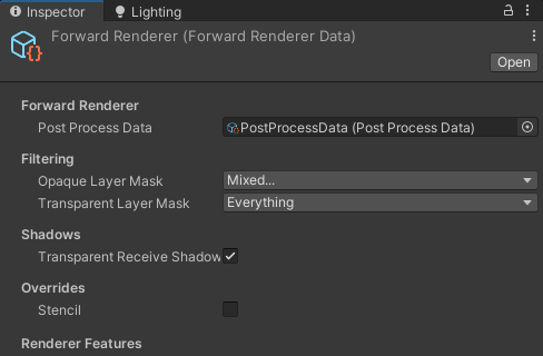
To set this up, we first need to set up a new “Card Object” Layer to put the object on, then on the Forward Renderer asset we exclude that layer from the Opaque Layer Mask. This means that layer will not be drawn automatically, as we want to handle rendering it ourself in order to use the overrides.
We can now add the RenderObjects feature to the list of features. Since we need to render the object after the card window we must put the Event to AfterRenderingOpaques.
Under Filters, we want to select Opaque and our “Card Object” layer. Then under Overrides, tick Stencil, set the Value to 2 and change the Compare Function to Equal. The Pass/Fail/ZFail can all be left as Keep.
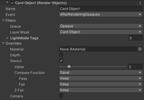
You should now see the object only when viewing it through the card window. If not, check the window is being drawn before the Card Object (the Frame Debugger window can be helpful) and make sure they both use the same reference value.
Something to bear in mind is that multiple cards use the same stencil value so objects can be seen through both. While it is possible to use different stencil values it is a bit awkward with the RenderObjects feature as you’d need a separate Layer for each (and there is a limit of 31 layers, some of which you’d want to use for other uses too). Objects behind the card can also still be seen through the window and can block viewing the object, unless you render everything else with Stencil, similar to the RenderObjects above but with the Compare Function as Not Equal.
An alternative to using stencils would be using additional cameras and Render Textures instead, which might be a bit more expensive but provides easier control over the sorting of multiple cards.
Thanks for reading! 😊
If you find this post helpful, please consider sharing it with others / on socials
Donations are also greatly appreciated! 🙏✨
(Keeps this site free from ads and allows me to focus more on tutorials)