Cloud Shader Breakdown
Intro
This shader is applied to a flat subdivided plane where vertices are offset vertically based on layered noise to create a cloud effect. Each layer of noise is offset by time at a different rate to simulate the clouds changing shape over time. It also uses the depth buffer to fade the alpha where there are intersections with other scene objects, which helps give the clouds a much softer appearance.
Notes
- This is an Unlit shader. Transparent surface mode and Alpha blending.
- Intended more for an “above the clouds” feeling, but the plane could be turned upside-down for clouds in the sky instead. You may want to remove the “depth intersection” part if objects aren’t going to intersect with the clouds to make the shader more performant.
- As we are writing this in Shader Graph, we are (currently) unable to add any tessellation to the shader, so instead we are using a custom plane mesh that has already been subdivided a lot to ensure the vertex manipulation is smooth. Depending on the camera angle required it might also be possible to have a disc or pizza-slice shape, subdivided more at the center and move the position/rotation along with the camera, rather than having multiple planes to make up the clouds.
- Since we are offsetting vertices it can cause geometry to overlap and this can cause sorting issues with transparent objects. If the shader writes to the depth buffer it would fix this, more info at the end of the post.
Breakdown
To begin we’ll set up the noise for our clouds. We’ll be using a mixture of Gradient Noise and Simple Noise nodes to do this – although you may also want to think about replacing some layers of noise with a seamless texture as a cheaper alternative.
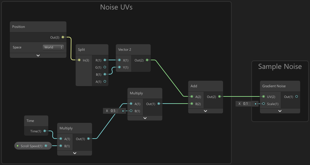
In order to ensure we can use multiple plane objects and have no seams between them, we can set the UVs of the noise to be based on the Position node set to World space. That gives us a Vector3 but the UVs are a Vector2 so we also need to Split it and take the X/R and Z/B coordinates to make our noise be based horizontally along the plane.
We can use a Time node to offset this position so the noise moves slowly over Time, with a Multiply node to control the speed at which the noise scrolls at. We’ll also add an overall speed multiplier as a Vector1 property so we can control the cloud scroll speed from the inspector.
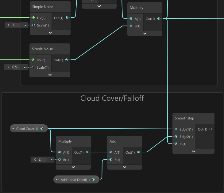
We’ll use parts of this noise setup 3 times, one for the Gradient Noise and two Simple Noise nodes, all moving at slightly different rates as shown in the image below.
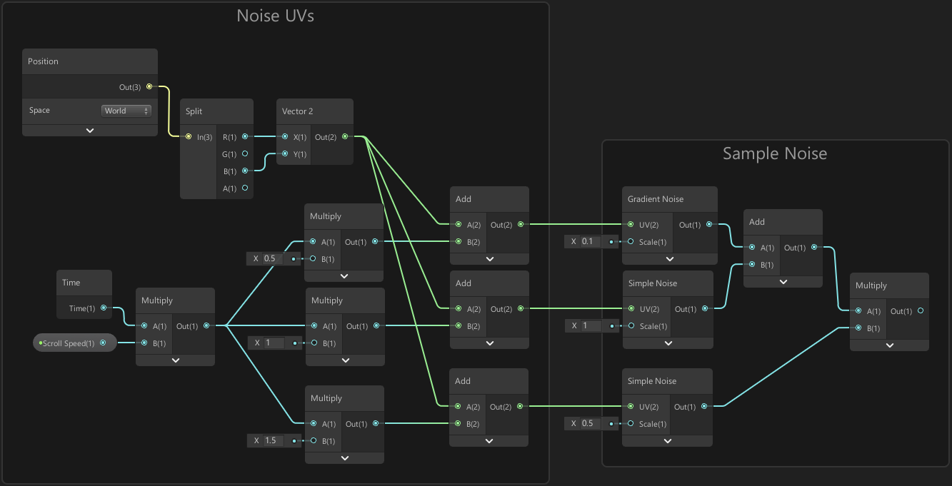
I’ve used a mixture of Add and Multiply to combine these layers of noise. We could take an average of all three (by adding them together and dividing by 3), but having a multiply in there made the layered noise output a bit more interesting, in my opinion at least.
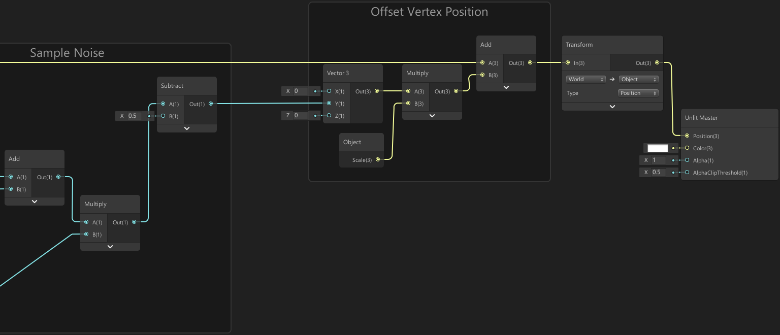
We can now use our layered noise output to offset the vertex position. In order to ensure this is only a vertical offset, we’ll first put it into the Y input on a Vector3 node, with the other two inputs set to 0. We can then Multiply this by a value to control the scaling – I’m using the object’s scale for this, so that we can easily change it by adjusting the Y scale of the plane rather than having a separate property – But if you want to be able to apply this to meshes other than a plane, you might want to use a property instead.
Also note that we are offsetting the World space vertex position here, but the Master node wants a Object space position, so we need to use a Transform node to convert it (from World, to Object).
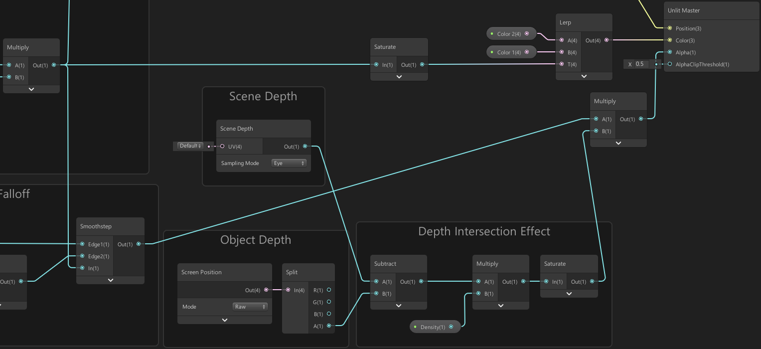
Next we’ll handle the cloud colour as it’s currently hard to see anything we’ve done with the shader being a solid colour. I’m using the same output from our layered noise – giving the higher parts of the clouds a different colour to the lower parts. We can do this by putting the layered noise into the T input on a Lerp node, and set the A and B inputs to two Color properties. This creates a linear interpolation between the two colours, creating a gradient. At T=0 it outputs A, and at T=1 it outputs B.
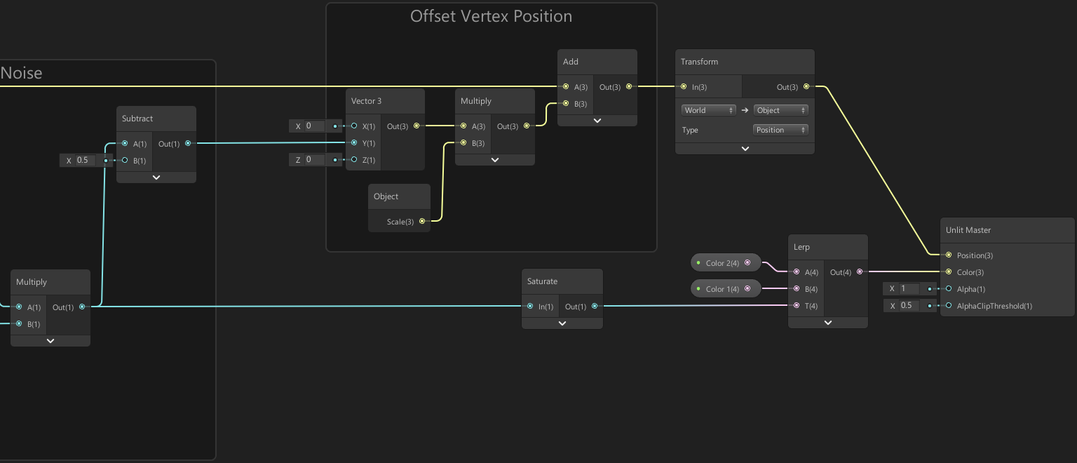
So we can control how much cloud cover there is, we can add a Smoothstep based on the layered noise output and use this as the Alpha input on the Master node. The Smoothstep is similar to a Step node, but provides a smoother transition where we specify two Edge inputs. If the In input is less than the first Edge it outputs 0 and if it is larger than the second Edge it outputs 1. Anything inbetween is an interpolation between 0 and 1, but it is not linear – it instead smoothly eases in and out.
I’m using a property to control the two Edge inputs. It outputs 1 if the Cloud Cover property is 0, as all noise values will be larger than 0, but as it gets larger the Smoothstep outputs 0 for the lower noise values, leaving only the higher parts behind. Also the falloff (which is controlled by Edge2) also increases, so the clouds also get softer, and we have an Additional Falloff property to control this further if required.
Finally, I wanted to add a depth intersection effect, so that objects fade into the clouds rather than having a harsh transition. We subtract the Object Depth from the Scene Depth, which we can then multiply by a value to control how it fades, aka the Density of the clouds. In order to obtain the Object Depth, we use the W/A component from the Screen Position node set to Raw mode. We can then Multiply this with the previous alpha affect to combine them.
This is a common technique to have effects where there are intersections with scene objects, such as with forcefields or shoreline effects on water shaders. Note however that this will only work in a Perspective camera projection. Also, on the (Lightweight / Universal) Render Pipeline Asset, the Depth Texture option needs to be enabled for the Scene Depth node to work.
If you aren’t going to have any objects intersecting with the clouds you’ll likely want to leave this part out for better performance.
Note : Also make sure the Alpha Clip Threshold on the Master node to 0 for URP. In older versions of LWRP the value would do nothing unless a node was connected but this has been changed. You may want to use an additional property to control this threshold in order to correctly render shadows if required, but this will create a hard-cutoff. If you don’t want to affect the normal visuals, you can create a Boolean Keyword with the reference of SHADERPASS_SHADOWCASTER to output different values when that is true, or use a Custom Function containing something like :
|
|
if (SHADERPASS == SHADERPASS_SHADOWCASTER) example in Intro to Shader Graph : Shader Pass Defines
Fixing Issues
That’s the Shader Graph complete – But before we finish the post I’ll try to tackle some issues…
Issue 1 : We need the shader to write to the depth buffer to prevent sorting issues (where planes overlap eachother), however it still needs to be in the Transparent queue in order to use Scene Depth.
URP v12+ (2021.2+)
- To fix this, should be able to enable “Depth Write” in Graph Settings.
- If this breaks the depth intersection effect, may need to leave this off and instead use the RenderObjects feature (on Universal Renderer asset) to re-render a Layer containing cloud objects, with the Depth Write override on.
URP (Prior versions)
- Should be able to use the RenderObjects feature (on Forward Renderer asset) to re-render a Layer containing cloud objects, with the Depth Write override on.
Issue 2 : URP versions prior to v7.1.1 (technically named Lightweight Render Pipeline (LWRP) back then) had a bug where the Screen Position result is based off the initial vertex position instead of the offset one. This causes the scene depth to not be properly aligned.
For newer versions you don’t need to worry about this. I imagine there aren’t many people using versions this old anymore - but just in case, either update to a newer version or can edit the generated code :
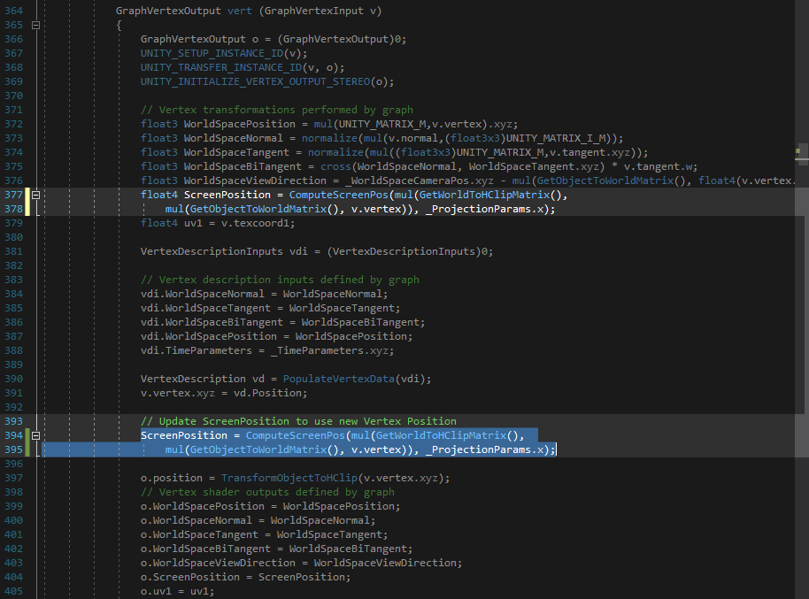
- Scroll through the generated code until we reach the “vert” function.
- From there, we should see a float4 ScreenPosition variable. Copy that line, without the “float4”, and paste it below the “v.vertex.xyz = vd.Position” line as seen in the image below.
Thanks for reading! 😊
If you find this post helpful, please consider sharing it with others / on socials
Donations are also greatly appreciated! 🙏✨
(Keeps this site free from ads and allows me to focus more on tutorials)