Intro to the Shader Pipeline
Hello! This post acts as a brief introduction to shader related concepts and how they are used to render graphics in Unity.
Sections :
- What is a Mesh?
- What is a Shader?
- Render Pipelines
- Shader Code
- Shader Passes
- Rendering Paths
- Other Types of Shaders
- Materials & Properties
- Setting Properties from C#
- Global Shader Properties
- Material Instances & Batching
- SRP Batcher
What is a Mesh?
A mesh contains the data for a 3D model, typically consisting of vertices and how they connect into triangles. Each triangle is made up of 3 vertices - though a vertex can be shared between multiple triangles (so there won’t always be triple the amount of vertices than triangles).
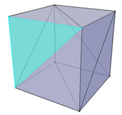
Example Cube Mesh, consisting of 12 triangles. In Blender (3D modelling software), this has 8 vertices, however this value may change when importing into Unity depending on whether it’s per-vertex data is the same between shared vertices.
The terms “mesh” and “model” are usually used as interchangeable words. But if we are being specific, a mesh always refers to the geometry (vertices/triangles) while a model may refer to the imported file, which can actually contain multiple objects, as well as materials, animations, etc. When a model has an object with multiple materials applied, Unity imports these as sub-meshes stored within the mesh. These sub-meshes share the same vertices array, but have different triangle arrays - corresponding to an element of the Materials array under the MeshRenderer component.
A model is commonly made in external 3D modelling programs, such as Blender, and imported into unity (usually using the .FBX format) but we can also generate (and/or edit) a Mesh at runtime using the methods in the C# Mesh class.
When we mention “vertex” we are usually referring to it’s position in 3D space, but every vertex in the mesh can contain many pieces of data. This includes data such as :
- Position in 3D space (Object space, so (0,0,0) is at the origin of the mesh).
- UVs, also known as Texture Coordinates as they are most commonly used for applying a texture to the model. These coordinates are typically Vector2 (two floating point values, each axis labelled as either xy or uv) but the actual UV channels can be Vector4, so can contain up to 4 floats in order to pass data in. See Mesh.SetUVs.
- Normals (a direction used for shading. Some modelling programs (e.g. Blender) may also use these to determine the winding order of the vertices, which shows which way the face is pointing. It is possible in a shader to cull the front or back side of a face when rendering)
- Tangents (a direction perpendicular (90 degrees) to the normal that follows the meshes surface along the horizontal texture coord (uv.x). Used for constructing Tangent Space, which is important for shading techniques such as Normal/Bump Mapping)
- Vertex Colours (a colour given to each vertex)
While two vertices may share the same position in 3D space, if their other data doesn’t also match then they must be two separate elements in the vertex data arrays.
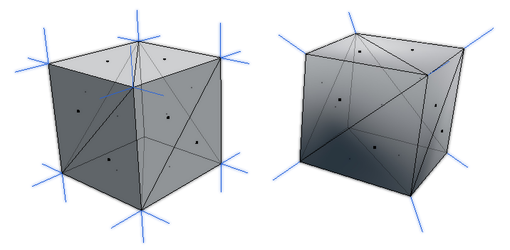
Example Cube Mesh. Both have 12 triangles but the left has 24 vertices, while the right has 8 vertices.
This is quite common if a model has flat shading rather than smooth shading like in the image above. Flat shading will increase the number of vertices because the Vertex Normals need to point in different directions depending on which face they are a part of. (This might not happen in the modelling program itself, but would when it’s exported to Unity). Smooth shading instead takes an average of these directions, so those vertices can be shared, assuming all other data is also the same!
What is a Shader?
A Shader is code that runs on the GPU (Graphics processing unit), similar to how a C# script is for the CPU. In Unity a single “.shader” file contains a shader program, which usually contains multiple “passes” that are used to render a mesh. Each pass contains a Vertex shader and Fragment shader (sometimes also referred to as a pixel shader). (Perhaps slightly confusingly, it’s common to use “shader” to refer to the specific stages, as well as the shader program/file as a whole).
The vertex shader runs for each vertex in a mesh and is responsible for transforming the 3D vertex positions (object space) from the mesh into Clip space positions (positions used to clip geometry to only render what is visible by a camera. There’s a few extra steps to turn this into a 2D screen position. I’ll hopefully be going over spaces in more detail in a future post). It also should pass other data that will be needed for calculations into the fragment stage, such as data from the mesh (UVs, normals, etc).
For tools like Shader Graph, this is mostly handled for us but it’s still very important to recognise there is two separate stages going on here - though this should be pretty clear as the Master Stack separates the output ports into Vertex and Fragment stages (as of Unity 2020.2+). The Position port (under the Vertex stage) is exposed for us to override the object space position before it is transformed to clip space, e.g. for Vertex Displacement. We can also override the Normal and Tangent that is passed to the fragment stage (important for lit shading to be correct). Shader Graph will automatically use data from the mesh if these ports are left blank.
For each triangle, and vertex in that triangle, the clip space positions passed out from the vertex stage is used to create fragments during a stage known as Rasterization. You can think of these fragments as “potential pixels” on the 2D screen (though multiple triangles can of course overlap which means fragments can be discarded or blend with the current pixel colour).
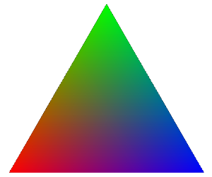
All of the per-vertex data passed into the fragment shader also gets interpolated across the triangle. A common example is while each vertex can specify a single vertex colour, a fragment shader outputting this results in blended colours.
The fragment shader runs for each of these fragments (potential pixels) and determines its colour that will be drawn to the screen (and in some cases, outputs a depth value too). This could be outputting a solid colour, using vertex colours, sampling textures, and/or handling lighting calculations to produce a more complex shading - where the name “shader” comes from.
In some cases, we might also want to intentionally discard/clip a pixel from being rendered (e.g. alpha clipping/cutout shader)
Render Pipelines
Unity has a few render pipelines which completely changes how rendering works. The default is the Built-in Render Pipeline (BiRP) which many older tutorials and assets are designed to work with. But in 2018/19 Unity also introduced Scriptable Render Pipelines (SRPs) such as :
- Universal Render Pipeline, intended to work across many platforms. It’s mostly equivalent to BiRP, but is meant to be more optimised and customisable. (Known as “Lightweight Render Pipeline (LWRP)” prior to Unity 2019.3)
- Note this is also somewhat separated into two - You have the option to use the “Universal Renderer Asset” (meant for 3D) and the “2D Renderer Asset” which gives access to URP’s 2D Lighting System.
- High Definition Render Pipeline, intended for high-end platforms to create cutting-edge, high-fidelity graphics.
- Also possible to write your own Custom Scriptable Render Pipeline. That page has some info, there’s also some tutorials such as this series by CatlikeCoding (and it’s continuation).
I’m not going into a huge amount of detail here but it’s important to know these pipelines exist as many Shaders and Assets are created for one or more pipelines and may not work in others. As much of the ShaderLibrary code is different, it is not possible to convert custom .shader files from one pipeline to another and they often need rewriting instead. For the built-in shaders, each pipeline usually has an equivalent and there are some tools to convert materials if upgrading a project. The docs linked above have instructions, (Always a good idea to back-up the project before upgrading!)
When creating a new project, there are also templates for each of these pipelines, as well as sample scenes.
One of the main advantages of these scriptable render pipelines is they support the SRP Batcher - which makes drawcalls (rendering objects to the screen) cheaper. Tools such as Shader Graph and VFX Graph (node based editors for writing shaders and creating particle effects respectively) were also created with these newer pipelines in mind. (Though the Built-in RP does support Shader Graph as of 2021.2).
For beginners, I’d recommend using URP & Shader Graph.
Shader Code
In Unity shaders are written HLSL (High Level Shading Language), though you’ll typically also see it referred to as CG, especially when dealing with the Built-in RP.
In a .shader file, you’ll always see this shader code between CGPROGRAM / HLSLPROGRAM and ENDCG / ENDHLSL tags. (You might also see CGINCLUDE / HLSLINCLUDE which includes the code in every shader pass). Shaders for URP/HDRP should always use the HLSL versions of these tags as the CG ones include some extra files which aren’t needed by those pipelines. It will cause the shader to error due to redefintions in their shader libraries.
The rest of the file is written in a Unity-specific syntax known as ShaderLab, which includes blocks such as “Shader”, “Properties”, “SubShader”, and “Pass”. You can find documentation for this Shaderlab syntax in the docs pages here.
Technically Shaderlab has some legacy “fixed-function” ways of creating shaders which means a CG/HLSL PROGRAM isn’t needed, but I wouldn’t worry about learning these as they are outdated and programming the shader is much more useful.
Alternatively there are also node-based shader editors, such as Shader Graph (official, avaliable for URP, HDRP and Built-in RP as of Unity 2021.2+), Amplify Shader Editor (but not free), and Shader Forge (no longer developed, only works on older Unity versions).
Even if you’re working with graphs/nodes, these tools will generate shader code files behind the scenes. Knowing some HLSL can also be useful for Custom Function/Expression nodes which allow you to write code in the graph or call a function from a .hlsl file.
Shader Passes
Shaders can contain multiple subshaders and passes. The RenderPipeline tag is useful to tell Unity which pipeline the SubShader is intended for if the shader needs to support multiple pipelines. While the LightMode tag is important to tell Unity what a pass is used for.
If Unlit (meaning unaffected by lighting, always fully lit), the “main” pass is typically one without a LightMode tag specified. For Lit shaders it should be tagged “UniversalForward” (URP), “ForwardBase” (Built-in Pipeline) or “Forward” (HDRP), assuming the shader needs to support Forward Rendering (next section will explain this in more detail).
|
|
In URP and the Built-in RP there is usually also a ShadowCaster pass in the shader program, which as the name suggests, allows the mesh to cast shadows. Each pass has its own vertex and fragment shader. In this case, the vertex shader uses the shadow bias settings to offset the vertices a little, which helps prevent shadowing artifacts. The fragment shader here usually just outputs 0 (black) as it’s colour isn’t that important. It only needs to discard/clip the fragment if a shadow shouldn’t be cast for that pixel.
There’s also a DepthOnly pass used in URP and HDRP which is very similar to the ShadowCaster but without the bias offsets. It allows a Depth Prepass to occur, which is sometimes used to create a Depth Texture. You can find more information about that in the Depth post. In the Built-in pipeline I believe it doesn’t have this pass, so the Depth Texture is instead created using the ShadowCaster pass.
Depending on the pipeline, there may be more passes that a shader can include. You can find some listed on the PassTags docs page for the built-in pipeline. Looking at the built-in shaders is also a good way to find out about each pass. You can download the built-in pipeline shaders source via the unity download page, and also find source for URP and HDRP via the Graphics github.
When using Shader Graph and other node editors, most of these “extra” passes are handled for us. We only really focus on that main Unlit or Forward pass that outputting to the colour buffer. If alpha clipping is enabled the graph will automatically handle this in other passes like the ShadowCaster & DepthOnly. But if you want to be able to include different alpha values per-pass for example, you can do so with a Custom Function node as explained here - Intro to Shader Graph : Shader Pass Defines.
Rendering Paths
Forward
Forward rendering can be considered the “regular” way of rendering things, where the shader calculates the pixel colour that is directly drawn to the screen.
Every fragment produced by the mesh has to do light calculations, even if it gets covered by another fragment in the same mesh or another object (though opaque objects closer to the camera tend to be drawn first to minimise this). Because of this there is typically a limit to the number of realtime lights that can affect each GameObject. In URP this is 1 Main Directional + 8 Additional Lights. Built-in has a similar limit but I think it can be increased in the graphics/quality settings (though with a performance penalty).
In URP there is also a light limit per camera :
- Desktop and console platforms: 256 Lights
- Mobile platforms: 32 Lights. OpenGL ES 3.0 and earlier: 16 Lights.
Forward+
As of Unity 2022.2+, URP also provides a Forward+ path which acts similar to Forward but clusters additional lights together based on screenspace-tiles, to be able to render more of them in a performant way.
This removes the limit for lights per-GameObject, but the limit per-camera still applies.
To support this, shaders should include the _FORWARD_PLUS keyword (renamed to _CLUSTER_LIGHT_LOOP in Unity6+) and the additional lights loop should be written in a particular way using macros from URP’s ShaderLibrary. As examples, see the AdditionalLights_float function in my Shader Graph Custom Lighting repo or the UniversalFragmentPBR/UniversalFragmentBlinnPhong functions in the URP Shader Library - Lighting.hlsl.
https://docs.unity3d.com/6000.1/Documentation/Manual/urp/rendering/forward-rendering-paths.html
Deferred
Deferred Rendering (or Deferred Shading) also has the advantage of having no limit to the number of lights per GameObject because the lighting is handled later in the pipeline on each screen pixel inside the volume of the light. Having more lights will still effect performance, but only if their ranges are very large on the screen. Though this only works with opaque geometry - Transparents are still be rendered in Forward.
However in order for this to work, there needs to be a bunch of additional buffers (known as geometry buffers / g-buffers) - storing per-pixel data like Albedo (aka Base Color) & Occlusion, Specular & Smoothness, Normals, and Emission & GI, taking up more memory compared to Forward paths.
The deferred pass renders to these buffers at the same time by using Multiple Render Targets (MRT). This isn’t supported on all platforms - so some may be limited to using Forward instead.
These g-buffers are then sampled later during a full-screen pass which handles the lighting/shading calculations and outputs the final colour for each pixel. It’s sometimes possible to override this with a custom shader - though isn’t documented and tends to be quite complicated. But useful if you want custom lighting such as toon/cel shaded for the entire scene.
- For Built-in RP there’s some tutorials of this, such as this Deferred article by Xibanya / Team Dogpit.
- For URP, I believe you can override the shader/material if using the Debug version of the Inspector on the URP Asset (or Universal Renderer Asset?). You’d likely want to use the default StencilDeferred.shader (and StencilDeferred.hlsl include) as an example/basis.
- I’m not familiar with HDRP and it’s likely not designed to be edited there - but probably possible if you fork the package.
These deferred tutorials may be useful for further reading :
- https://catlikecoding.com/unity/tutorials/rendering/part-13/
- https://gamedevelopment.tutsplus.com/articles/forward-rendering-vs-deferred-rendering--gamedev-12342
Here’s some docs pages related to these Rendering Paths which may provide more info/comparisons :
- BiRP : https://docs.unity3d.com/Manual/RenderingPaths.html
- URP : https://docs.unity3d.com/Packages/com.unity.render-pipelines.universal@16.0/manual/urp-universal-renderer.html
- HDRP : https://docs.unity3d.com/Packages/com.unity.render-pipelines.high-definition@16.0/manual/Forward-And-Deferred-Rendering.html
Other Types of Shaders
In the built-in pipeline there’s also Surface shaders, (which you can usually identify by the “#pragma surface surf” and “surf” function). Behind the scenes these generate a vertex and fragment shader while also handling calculations, such as lighting and shadows for you. However these types of shaders do not work in URP and HDRP (though possibly in the future there will be a SRP version). Shader Graph’s PBR (or HDRP’s Lit) Master nodes are already quite similar to surface shaders if you’re okay with working with nodes.
As well as vertex and fragment shaders, there are other stages that can be involved for more complicated techniques, such as :
- Tesellation (domain and hull shaders), which convert triangles into smaller triangles, usually based on viewing distance, in order to add more detail to the mesh.
- Geometry shaders, which can add new geometry (e.g. triangles) for each vertex/triangle already in the mesh. For example, producing grass blades. It is worth nothing that the performance of geometry shaders isn’t great and there may be better methods to achieve a similar effect.
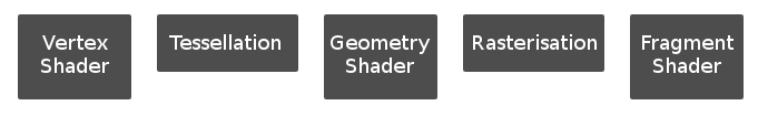
Shows how these extra stages fit into the pipeline.(Though this is simplified and doesn’t include steps like clipping, face culling, early z-test, z-test, blending, etc)
These additional shader stages aren’t needed for every shader program, and aren’t always supported on each platform/GPU. Both of these also aren’t included/possible in Shader Graph (yet), so I won’t be going over them in this post. You can likely find some examples for shader code online though, such as :
- https://catlikecoding.com/unity/tutorials/advanced-rendering/tessellation/
- https://halisavakis.com/my-take-on-shaders-geometry-shaders/
- https://roystan.net/articles/grass-shader.html
- https://github.com/Cyanilux/URP_GrassGeometryShader
There is also Compute shaders, which run separately from the other shaders mentioned above. They are typically used for generating textures (e.g. an output using RWTexture2D
- https://www.ronja-tutorials.com/2020/07/26/compute-shader.html
- http://kylehalladay.com/blog/tutorial/2014/06/27/Compute-Shaders-Are-Nifty.html
- https://lexdev.net/tutorials/case_studies/frostpunk_heatmap.html
Materials & Properties
From a shader we can create Materials, which acts as containers for certain data (such as floats, vectors, textures, etc). This data is exposed by the shader using the Properties section of the Shaderlab syntax (or the Blackboard in the case of Shader Graph). These properties can then be edited for each material in the inspector.
|
|
This allows multiple materials to share the same shader, but we can change textures and other settings to change how the result looks.
For example, the Standard shader that Unity provides (or URP/Lit, HDRP/Lit), can replicate many basic materials fairly well (e.g. plastic, metal, wood, stone, etc.) with the correct texture maps and other values (Albedo, Normal, Occlusion, Metallic/Specular, etc)
Setting Properties from C#
In order to set one of these properties from C#, we need a reference to the Material object and need to know the property name (Reference field in Shader Graph). In order to get the material we can do a few different things. One way is to use a public field :
|
|
Then assign the material in the inspector. Setting the properties on the material using this method will always affect all objects that share that material though.
Alternatively, we can keep the material private and set it based on the value in the Renderer. e.g.
|
|
This assumes the script is on the same GameObject as the Renderer (e.g. MeshRenderer).
We can then set a property using one of the “Set” functions. e.g. SetFloat, SetVector, SetTexture, SetColor listed under the Materials docs scripting page. This could be in Start or Update (though it’s better to only call it when the value actually needs to be changed).
|
|
Here the “_ExampleColor” would be the name/reference of the property as defined in the shader. Typically, if you select the .shader (or .shadergraph) file in the Project window it will list the properties it has in the Inspector window.
You can also find them listed in the Properties section of the Shaderlab code. For Shader Graph, this is the “Reference” field that each property has, not to be confused with its display name.
Typically the reference starts with “_” as a naming convention. I believe this also helps to avoid errors as without it the reference might be something that is used by the shaderlab syntax already, but don’t quote me on that. (e.g. “Offset” might error because of its shaderlab usage, but “_Offset” wont? Same with Cull, ZTest, Blend etc.)
Global Shader Properties
There are also Global shader properties, which can be set through the Shader class and it’s static “SetGlobal” functions. e.g. SetGlobalFloat, SetGlobalVector, SetGlobalTexture, SetGlobalColor, etc.
|
|
In this example, the “_GlobalColor” property can be defined by any shader that needs access to the colour in the same way a regular property would be used, except it doesn’t need to be in the exposed Shaderlab Properties section.
In Shader Graph, each property in the Blackboard has an Exposed tickbox instead. Unexposed ones won’t appear in the material inspector but can still be set by using these SetGlobal functions.
Material Instances & Batching
It’s important to understand the difference between renderer.sharedMaterial and renderer.material when dealing with obtaining the material to change it’s properties.
Using .sharedMaterial, as the name might suggest gives you the material shared by all objects. This means that changing a property on it will affect all objects (similar to setting properties on a public Material).
Using .material instead creates a new instance (clone) of the material the first time it is called, and automatically assigns it to the renderer. Setting a property using this will only affect that object. However note that it is also your responsibility to destroy this material instance when it is no longer needed. e.g. in OnDestroy :
|
|
Typically for the built-in pipeline using many material instances is bad, as it breaks Batching - which typically combines meshes that use the same material together so they can be drawn all at once, rather than separately. This can help with performance - though it is worth noting that since it combines meshes, certain data (like the Model matrix, UNITY_MATRIX_M / Unity_ObjectToWorld and inverse ones) is no longer on a per-object basis which may lead to unintended results if the shader relies on Object space.
When referring to batching, there’s a few difference types, see docs pages linked below for more details :
- Static Batching - Requires GameObjects to be marked as static (or at least have the “Batching Static” flag enabled). This combines meshes that share the same material into one large mesh, in order to reduce the number of draw calls required to render those objects.
- Dynamic Batching - Always used for Particles, Sprites. Can be enabled for meshes too (would likely only do this in Built-in RP). Similar to static batching, but according to the docs vertices are transformed into world space on the CPU. On modern devices, this can be more expensive than the regular draw call overhead.
- SRP Batching - For SRPs (e.g. URP, HDRP, Custom SRP). This batches the setup between draw calls in order to make them cheaper, rather than combining meshes. Material data is also persistent on GPU. Next section goes into a bit more detail.
Similar to batching, another way to draw lots of objects together but still have different material values is to use GPU Instancing and Material Property Blocks together. MPBs can also be used without GPU Instancing, however it will still lead to separate draw calls so there will be little performance benefit without also making the shader support instancing.
SRP Batcher
The Scriptable Render Pipelines (URP or HDRP) also have another method of batching - the SRP Batcher.
Rather than combining meshes / draw calls, it batches the setup between those draw calls. According to the docs page, materials also have persistent constant buffers (UnityPerMaterial CBUFFERs) located in GPU memory, that would only need updating when properties change.
This type of batching works even with different material instances (as long as they share the same shader variant - they won’t batch if materials use different keywords or shaders). So in the SRPs (URP, HDRP and Custom SRP), it’s actually safe to use renderer.material to edit properties without breaking these batches. They’ll likely still produce some memory overhead though. Of course, you should still use .sharedMaterial to avoid creating instances where they aren’t necessary.
Also, since the SRP Batcher doesn’t combine meshes, the Model matrix and it’s inverse stays intact. Object space can be used in the shader without the unintended results you would get with the other batching methods.
Shaders created using Shader Graph will automatically support the SRP Batcher, but custom HLSL code shaders need to define a UnityPerMaterial CBUFFER. This should contain all the per-material properties except for textures. Every pass in the shader needs to use the same CBUFFER values, so I’d recommend putting it inside the SubShader in HLSLINCLUDE tags, as this will automatically include it in every pass for you.
It also needs a UnityPerDraw CBUFFER, but this is set up automatically by URP/HDRP when using the correct include files.
The following example would work for URP (assuming these floats/vectors are also defined in the Properties block) :
|
|
You can find some full examples in my Writing Shader Code for URP (v2) article.
Note that Material Property Blocks will break batching via the SRP Batcher so must be avoided in URP/HDRP. You can see what is being batched by using the Frame Debugger window to check if it’s working properly or not (e.g. would be displayed as “SRP Batch” rather than Draw commands)
Thanks for reading! 😊
If you find this post helpful, please consider sharing it with others / on socials
Donations are also greatly appreciated! 🙏✨
(Keeps this site free from ads and allows me to focus more on tutorials)