Swapping Colours
Intro
Recently I’ve seen questions about adjusting/swapping colours of textures in the shader. Depending on the use-case there’s a few methods we can use, and while there are some resources out there I thought it would be nice to write a post of my own (or at least provide examples & links to other resources for additional reading).
Shader Graph examples are used, but I’ve also provided some links to the Shader Graph docs (Node Library) where you can view generated HLSL code.
Some specific use-cases I can think of include :
- Player/team colours, for example in RTS or multi-player party games, or for player customisation.
- Colour variations on environment props, foliage/leaves, enemy variants, etc.
- Adjustable colours and gradient ramps used for VFX / Particle Effects.
- Swappable colour palletes for pixel art (sprites / tilemaps). Could just be for aesthetics or tied to gameplay.
- also Post Processing effects, but that’s a bit outside the scope of this post
Typically these methods would involve some texture(s) as an input (though some may work with noise or procedural shapes produced from signed distance functions too). It also doesn’t matter if it’s intended for a 3D model, 2D sprite, UI, etc.
Some pros/cons :
- A main advantage is less texture memory is used compared to manually creating colour-variations and storing as separate textures (or larger atlas / texture array).
- Likely easier to tweak colour properties/fields on the material/scripts than editing texture files.
- The methods that alter the UV coords to the Sample Texture 2D node in the fragment stage (Gradient & Palette Texture sections) may be a bit more expensive (more noticeable on mobile platforms), as this produces what is referred to as a “dependent texture read”. My understanding is this results in the GPU not being able to do texture pre-fetches, so causes increased latency when reading/sampling texels. But it’s good to try multiple methods and compare/profile!
Sections
- Tint
- Lerp
- Tint Color Channels
- Mask Texture
- Replace Color Node
- Blend Node
- Gradient Ramp
- Palette Texture/Array
Tint
One of the simplest forms of adjusting colour is a tint, which typically involves a Multiply between our input and a given colour (Color node or property). Our input here would typically be a greyscale texture (a float value between 0 and 1). Values should ideally be close to 1 (white) so we get the full range of colour we can tint towards.
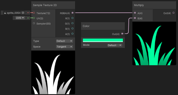
(Grass texture from Kenney assets - Foliage Sprites)
The colour here could use HDR mode, so we have control over the intensity too. (Though that would be more common for glowy particle effects, not grass!)
You’d typically also convert the Color node here to be a color property - that way it can be exposed to the material or allow setting it from C#. But I’ll be keeping them as nodes in the post so you can clearly see what colour has been assigned.
(If you aren’t familiar with properties, see my post : Intro to Shader Graph - Properties)
Lerp
In the above example, since we are multiplying, a value of 0 (black) in the input texture always results in black - but it is possible to have control over this colour too.
Assuming our greyscale/float input ranges between 0 and 1, we could invert it using a One Minus and tint with another colour (via Multiply), then Add the two tints together.
This is the same calculation as a linear interpolation, so it’s easier to use the Lerp node. Our greyscale input here goes into the T input, and A and B are the two colour nodes/properties.
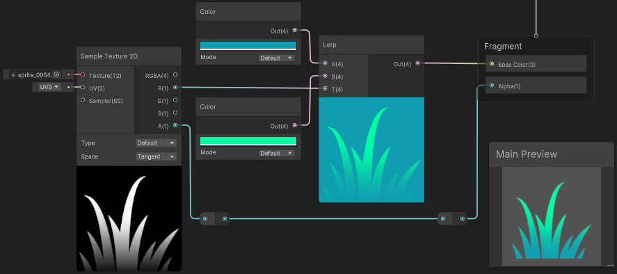
(Also note the grass texture has been edited to contain a darker gradient)
The “background” of the preview here looks cyan as the RGB data originally contained black pixels, but we don’t need to worry as the texture also contains an alpha channel (A output, connected to Alpha port on the Master Stack). This makes those pixels transparent in the final result - shown in Main Preview, as well as in scene/game. (Assuming the graph is set to Transparent surface mode, or using Opaque & Alpha Clipping)
As a quick side note, the Lerp node is also useful for layering multiple textures / masking areas too. In this case we’d use RGBA outputs from textures rather than Color node/properties. For more info/examples see : FAQ - Layering textures/colours
Additional notes about colour spaces
The above examples are interpolating through sRGB/linear color space (depending on the colour space set under project settings, see the docs page : Linear or gamma workflow). But there are other colour spaces we could interpolate through for different results. There’s no “correct” space to use here really, it depends on the result you want. These conversions between different colour spaces would make the shader slightly more expensive though.
For example, we could interpolate in HSV space. In shader graph, this could be handled with the Colorspace Conversion node. For example compare the following results :
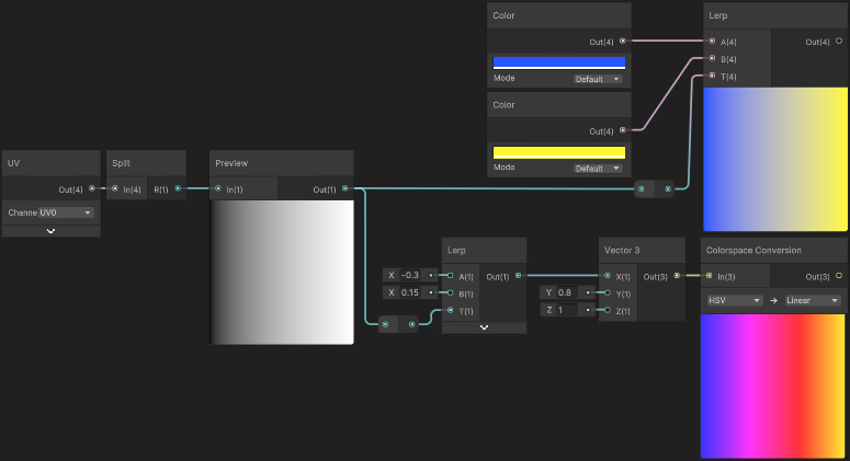
The project here is using Linear colour space. Lerping between blue/yellow results in a grey transition, while lerping through Hue (X input of Vector3, since we convert from HSV space) results in more of the colour spectrum. We could also interpolate other components but in this case the Saturation stays at 0.8 and Brightness at 1.
Can see the HLSL code each conversion uses in the Node Library - Colorspace Conversion or use/see functions under render-pipelines.core/ShaderLibrary/Color.hlsl.
For a much more in-depth look at this, also see this article by Alan Zucconi : The Secrets of Colour Interpolation
Tint Color Channels
We could also extend the tint method to obtain up to 3 or 4 colours by packing multiple greyscale/float inputs in each colour channel of the texture (red, green, blue, alpha).
In some cases the alpha channel may be required for transparency so can’t be used (quite common for sprites). But for other channels we can apply a (using a Multiply with a Color node or property) and then combine those together using Add nodes (or alternatively, Maximum).
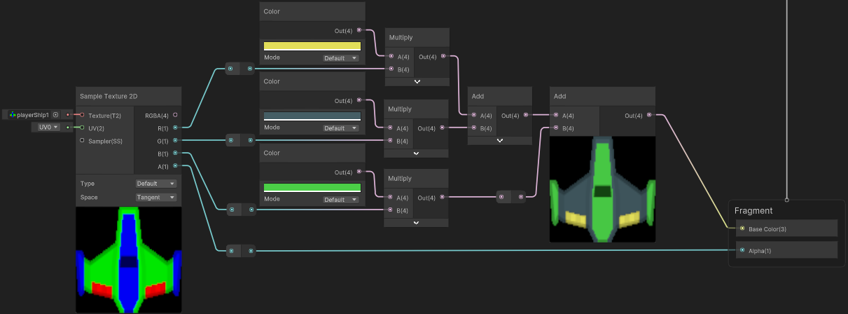
Spaceship is an edited sprite from Kenney Assets - Space Shooter Redux
If the alpha channel isn’t required for transparency (may be more common for 3D models), then we could that for tinting too. I find it easier to have this channel inverted as we can then use the rubber/eraser tool to “paint” areas with 0 alpha, and still see coloured areas. Programs typically also don’t store RGB data in areas with 0 alpha, and while there may be ways to override this behaviour, inverting the channel is easier.
To account for this in the shader we’d use a One Minus node before the Multiply
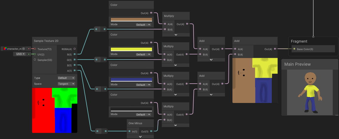
Another tint example where texture is applied to 3D character, contains some darker shades to fake some shading. Alpha channel is used to mask feet/shoes.
Mask Texture
Okay, but what if you don’t want to adjust the whole texture? In this case we could use another texture to mask the effect.
A common (though somewhat naïve) way to handle this is using a value of 1 (aka 255) in a channel of the mask texture (for the area you want to colour), and 0 elsewhere. This works okay with Point filter mode on the texture, but when using Bilinear (or Trilinear) it can cause white artifacts/seams to leak through around the edge. For textures on 3D models this may not be a problem if UV islands stay inside the mask (for example).
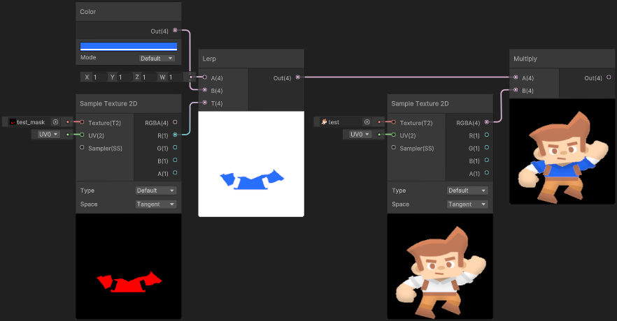
(Male Adventurer Sprite from Kenney assets - Toon Characters 1, though edited)
Note the white edges around the shirt in the final preview :(
For details on exactly why this occurs see this article by Ben Golus : The Team Color Problem. The alternative mentioned there is using a “pre-multiplied” input & mask - or in other words, separate the area you want coloured into a second texture, leaving black pixels in the regular one :
With these as inputs, we can then tint the mask texture and Add it to the other.
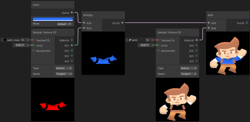
Better method of masking the tint - no white edges!
The mask is only using the red channel here - we could use the other channels to mask other areas. Or if only the red channel is required, the texture could be imported as a “Single Channel” type (set to “Red”) to save memory. Though then you may also need a Colorspace Conversion (RGB to Linear) on the texture output, if in Linear colour space (rather than Gamma).
Additional notes about sprites / transparent textures
When importing Sprites (or Default textures where “Alpha Is Transparency”) colours in fully transparent areas can stretch out in previews in Shader Graph. Don’t be worried - this is intentional as it helps to avoid artifacts, as explained here in faq.
If you’re wondering why this hasn’t occurred in these examples, I imported the main texture without an alpha channel as I wanted the example to be clearer. But even with an alpha channel and this colour stretching, the final result should look correct provided the A output from the Sample Texture 2D is connected to the Alpha port on the Master Stack.
However, the mask texture should still stay with a black background to avoid the colours stretching out. Though if it did have an alpha channel we could instead Multiply the R and A outputs before applying the tint.
Replace Color Node
Let’s also go over the Replace Color node that Shader Graph includes… (also Color Mask, which is essentially the same thing but without providing a colour to lerp to).
HLSL
|
|
As the name suggests, the node can be used to replace an existing colour with another. It can also select similar shades using the Range and Fuzziness inputs, but it can still pretty difficult to get it to do what you want. In practice, I’ve found it only really works well with pixel art.
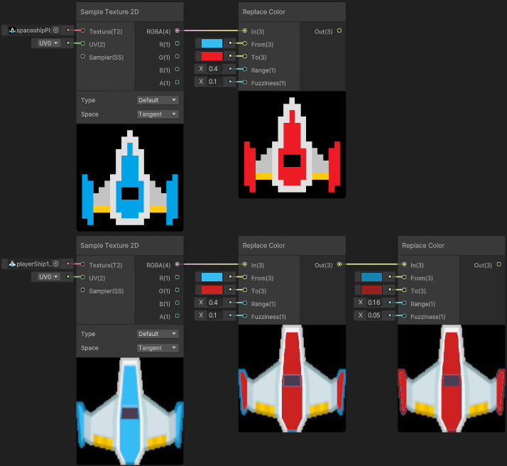
Node worked well on pixel art spaceship (that I made), but has left some edges/artifacts on the other sprite (from Kenney Assets - Space Shooter Redux). Perhaps with one of the alternative spaceship colours or edits to the sprite would make it work better - but the point is the Tint examples above produce better results and is cheaper!
One main advantage with using this method is you don’t need to edit the colours of the input texture, which may be why beginners are drawn to using it.
I’ve definitely seen a few tutorials out there using this node, but it’s actually not cheap as it calculates the distance between the In and From inputs (which uses a square root internally). For a few colours this may not be a big deal, especially if targetting high end platforms. But for mobile, the other methods in this post may work better.
Blend Node
We could also use a Blend node for different ways of mixing colours, similar to combining texture layers in image manipulation software like Photoshop, GIMP, etc. Behind the scenes these all use a Lerp but involve additional math which calculates the B input before the lerp.
The Overwrite mode in particular is directly equivalent to Out = lerp(Base, Blend, Opacity);
Some examples :
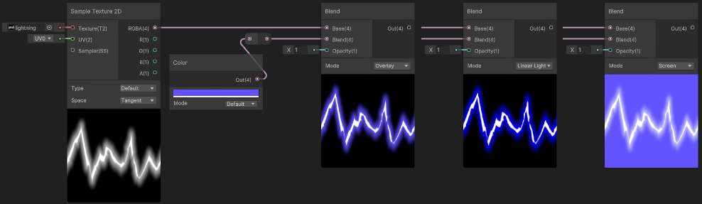
Blend nodes using Overlay, Linear Light and Screen mode.
In this example the texture is being put into the Base layer, and a colour is used as the Blend layer. The Opacity is set to 1 for full-strength of the blend (though it can also go above 1 as the interpolation is not clamped). An Opacity of 0 will always result in the same as the Base input.
If you’re interested in the HLSL code the different blend modes use, see Node Library - Blend.
Gradient Ramp
We can also use a gradient (also sometimes known as a ramp - especially when using solid colour bands rather than interpolated colour keys) to have better control over the resulting colours from a greyscale (0-1 float) input.
This could be seen a series of remaps & lerps that combine together, which is how the Gradient object and Sample Gradient node works in Shader Graph behind the scenes. You can see some example HLSL code in the Node Library - Sample Gradient.
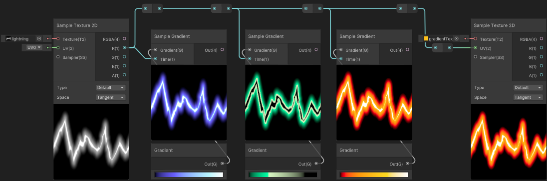
However Shader Graph does not support exposing these gradient objects to the material or C# - which makes them much less useful. I have listed a few alternatives in my post : Intro to Shader Graph - Gradient, but the one I’d recommend is storing the gradient as a Texture2D and use Sample Texture 2D instead which can also been seen in the image above. Note that the texture should also be set to Clamp wrap mode.
Some examples where this specifically might be used :
- VFX / Particle Effects, like the Lightning above. Also see this article (written for UE4 but has some good examples)
- Toon shading (typically involves a greyscale ramp to control the banding, which is then additionally tinted/lerped to add colour)
- Stylistic Fog (from Firewatch), for Built-in RP also see this recreation by Harry Alisavakis
Palette Texture/Array
The concept of this Gradient/Ramp could also work for pixel art, but rather than having colours interpolate, we could have neighbouring values point to completely different colours. In this case the input texture uses specific values which corresponds to the x coordinate of a texture (or index of an array) that contains our palette.
Assuming the input texture is a RGBA32 format we’ll be dealing with 8-bit channels, meaning it can store values 0-255 (though in the shader it’s still 0-1). That means 256 unique indices we could support, so the palette (texture or array) could contain up to 256 colours. (Using red channel only. If you were to use the red and green channels to sample a 2D palette, it could support up to 65536 colours, though that seems quite uncessarily large imo)
(This also assumes the input texture settings use Point filter mode and Compression : None)
Here’s an example with just 5 colours :
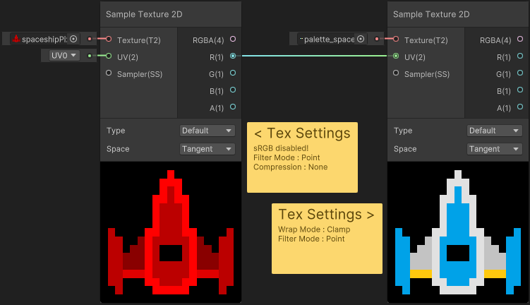
Note that sRGB has been disabled on the input texture. The palette texture also uses Clamp wrap mode.
The palette texture size here is 5x1 (containing black, lightGrey, lightBlue, yellow and white)
Values stored in the input texture are multiples of 255/(5-1) (so 0, 63.8, 127.5, 191.3, and 255). The input texture here still contains an alpha channel though you could consider “fully transparent” to be another colour for the palette (so 6x1 and multiples of 255/(6-1) instead), then the input could be imported as a single-channel texture to potentially save on memory space.
One problem with this method is it’s not really easy to manually create textures storing these indices (especially with large palettes as the shades would be very close to eachother). But you could use an editor C# script to bake/generate them. I haven’t got a script to share here, but I imagine it would be something along the lines of :
- for each pixel in a coloured pixel-art texture,
- loop through the palette texture/array to locate which colour matches, with it’s index,
- set pixel in generated texture to
new Color(index / (paletteSize-1), 0, 0, inputPixel.a)
Additional notes if storing the palette as an array
If storing the palette as an array :
- Would need to convert the 0-1 greyscale value to an index.
- e.g.
(int)(In * numberOfColours - 1)
- e.g.
- I’ve heard that accessing an array may be slightly quicker than a texture lookup (though as always, you should try both and profile on the target platform to really see if it makes a difference)
- Materials don’t support serialisation for arrays, so they aren’t exposed to the material - but can be set from C#. There is Material.SetColorArray, however in the scriptable render pipelines (e.g. URP/HDRP) we should only set arrays globally (via Shader.SetGlobalVectorArray) to avoid issues related to the SRP Batcher.
- Of course this means everything would be using that same palette array, but if you want to swap the palette per-object it should still be possible by providing an offset (via a Float property), which could be used to shift the index (Add). In this case our array would actually store multiple palettes.
- It’s not documented but I believe arrays are also limited to a maximum length of 1023 though, so this would limit the number of palettes you can have. If that’s a problem, using a texture instead may be better.
- If the project is using Linear colourspace, May also experience issues with gamma/linear colourspace differences as the functions mentioned above don’t deal with this. This can be fixed by using .linear on the Color object before putting it into the array. When setting globally you’ll also need to manually cast your colours to fill a Vector4[] array as there’s no “SetGlobalColorArray” function.
Thanks for reading! 😊
If you find this post helpful, please consider sharing it with others / on socials
Donations are also greatly appreciated! 🙏✨
(Keeps this site free from ads and allows me to focus more on tutorials)